Rheem RARL-JEC Installation Instructions - Page 19
Command for Compressor Operation Y1 LED, First Stage Cooling Operation, Second Stage Cooling
 |
View all Rheem RARL-JEC manuals
Add to My Manuals
Save this manual to your list of manuals |
Page 19 highlights
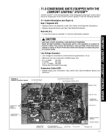
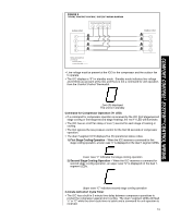
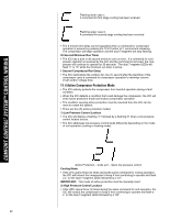
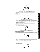
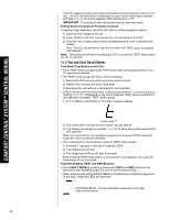
COMFORT CONTROL2 SYSTEM™ CONTROL WIRING FIGURE 5 TYPICAL COMFORT CONTROL2 SYSTEM™ WIRING DIAGRAM Indoor Unit Communicating Thermostat 1 2RC 1 2 R C WIRING INFORMATION Line Voltage -Field Installed - - - - - -Factory Standard Outdoor Unit 1 2 R C • Line voltage must be present at the ICC for the compressor and the outdoor fan to operate • The ICC displays a "0" for standby mode. Standby mode indicates line voltage and 24VAC are present at the ICC and there is not a command for unit operation from the Comfort Control2 thermostat. Zero (0) displayed The unit is in standby Command for Compressor Operation (Y1 LED) • If a command for compressor operation is received by the ICC (first stage/second stage cooling or first stage/second stage heating), the red Y1 LED will illuminate. • The ICC has an on/off fan delay of one (1) second for each stage of heating or cooling. • The ICC ignores the low pressure control for the first 90 seconds of compressor operation. • The dual 7-segment LED displays five (5) operational status codes. 1) First Stage Cooling Operation - When the ICC receives a command for first stage cooling operation, a lower case "c" is displayed on the dual 7-segment LEDs. Lower case "c" indicates first stage cooling operation 2) Second Stage Cooling Operation - When the ICC receives a command for second stage cooling operation, an upper case "C" is displayed on the dual 7segment LEDs. Upper case "C" indicates second stage cooling operation 3-minute Anti-short Cycle Timer • The ICC has a built in 3-minute time delay between compressor operations to protect the compressor against short cycling. The dual 7-segment LEDs will flash "c" or "C" while the short cycle timer is active and a command for unit operation is received. 19
-
 1
1 -
2
-
3
-
4
-
5
-
6
-
7
-
8
-
9
-
10
-
11
-
12
-
13
-
 14
14 -
 15
15 -
 16
16 -
 17
17 -
 18
18 -
 19
19 -
 20
20 -
 21
21 -
 22
22 -
 23
23 -
 24
24 -
25
-
26
-
27
-
28
-
29
-
30
-
31
-
32
-
33
-
34
-
35
-
36
-
37
-
38
-
39
-
40
-
41
-
42
-
43
-
44
-
45
-
46
-
47
-
48
 |
 |
