Rheem RARL-JEC Installation Instructions - Page 18
Control Wiring
 |
View all Rheem RARL-JEC manuals
Add to My Manuals
Save this manual to your list of manuals |
Page 18 highlights
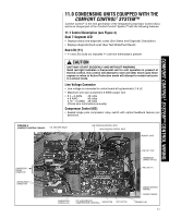
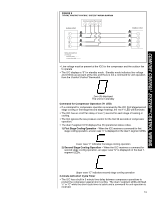
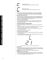
COMFORT CONTROL2 SYSTEM™ CONTROL WIRING Thermostat Connector (E2) • R - 24VAC from the indoor unit 24VAC transformer (40 VA minimum) • C - 24VAC Common from the indoor unit 24VAC transformer • 1-Data: System Communications Line 1 • 2-Data: System Communications Line 2 Low Volt Fuse • If required replace with 3 A automotive ATC style blade fuse Low Pressure Control (LPC Input) • Low-pressure control is factory installed • Low pressure control is an automatic resetting device High Pressure Control (HPC Input) • High-pressure control is factory installed • High pressure control is an automatic resetting device Ambient Temperature Sensor (included with all applications) • Included with all applications TEST and SW2 Buttons • TEST and SW2 buttons used to enter Test and Fault Recall Mode Memory Card • The memory card stores all unit information. • The unit information is called shared data. • The shared data is all the information needed for proper unit operation. 11.2 Comfort Control2 System™ Control Wiring The Comfort Control2 System™ consists of: • Serial communicating heat pump or condensing unit equipped with the Comfort Control2 System™ • Air handler or furnace equipped with the Comfort Control2 System™ • Comfort Control2 thermostat IMPORTANT: If the installed system does not meet these requirements, the system must be wired using traditional control wiring, reference Section 11.7 Conventional 24VAC Thermostat Control Wiring. The Comfort Control2 System™ requires four (4) control wires for unit operation: R - 24VAC C - 24VAC common 1 - Data wire 1 2 - Data wire 2 Note: Comfort Control2 System™ requires 18 AWG thermostat wire. Note: Term dip switches should be in "ON" position. If the low voltage control wiring is run in conduit with the power supply, Class I insulation is required. Class II insulation is required if run separate. Low voltage wiring may be run through the insulated bushing provided in the 7/8 hole in the base panel, up to and attached to the pigtails from the bottom of the control box. Conduit can be run to the base panel if desired by removing the insulated bushing. The Comfort Control2 air handler or Comfort Control2 furnace transformer is equipped with a 24 volt, 50 VA transformer for proper system operation. See the wiring diagram in Figure 5 for reference. Use Table 5 to size the 24-volt control wiring. The four 18AWG low voltage control wires must be installed from the thermostat to the indoor unit and from indoor unit to the outdoor unit. The wire length between the thermostat and indoor unit should not be greater than 100 feet. The wire length between the indoor unit and outdoor unit should not be greater than 125 feet. 11.3 Comfort Control2 System™ ICC Control Operation Installation Verification • 24V AC power on R&C must be present at the ICC for it to operate 18
-
 1
1 -
2
-
3
-
4
-
5
-
6
-
7
-
8
-
9
-
10
-
11
-
12
-
 13
13 -
 14
14 -
 15
15 -
 16
16 -
 17
17 -
 18
18 -
 19
19 -
 20
20 -
 21
21 -
 22
22 -
 23
23 -
24
-
25
-
26
-
27
-
28
-
29
-
30
-
31
-
32
-
33
-
34
-
35
-
36
-
37
-
38
-
39
-
40
-
41
-
42
-
43
-
44
-
45
-
46
-
47
-
48
 |
 |
