Ryobi RMX001 Operation Manual - Page 11
Installing The Wheels, Installing The Motor Assembly, Warning
 |
View all Ryobi RMX001 manuals
Add to My Manuals
Save this manual to your list of manuals |
Page 11 highlights
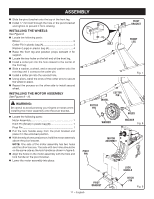
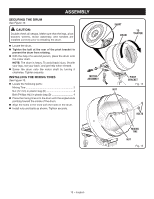
ASSEMBLY Slide the pivot bracket onto the top of the front leg. Install 17 mm bolt through the hole in the pivot bracket and tighten to prevent it from rotating. INSTALLING THE WHEELS See Figure 8. Locate the following parts: Wheel 2 Cotter Pin in plastic bag (A 4 Washer (Large) in plastic bag (A 4 Raise the front leg and position props beneath it for support. Locate the two holes on the left end of the front leg. Install a cotter pin into the hole closest to the center of the front leg. Slide a washer, a wheel, and a second washer onto the front leg until it contacts the cotter pin. Install a cotter pin into the second hole. Using pliers, bend the ends of the cotter pins to secure the wheel in place. Repeat the process on the other side to install second wheel. INSTALLING THE MOTOR ASSEMBLY See Figures 9 - 10. WARNING: Be careful to avoid pinching your fingers or hands when installing the motor assembly onto the pivot bracket. Locate the following parts: Motor Assembly 1 Hitch Pin (Small) in plastic bag (B 1 Pivot Pin 1 Pull the lock handle away from the pivot bracket and place it in the unlocked position. With the help of a second person, hold the motor assembly above the pivot bracket. NOTE: One side of the motor assembly has two holes and the other has one. The side with two holes should be on the same side as the lock handle as shown in figure 9. Align the holes on the motor assembly with the hole and lock handle on the pivot bracket. Lower the motor assembly into place. BOLT PIVOT BRACKET FRONT LEG Fig. 7 WHEEL COTTER PIN COTTER PIN HOLES WASHER WASHER Fig. 8 PIVOT PIN MOTOR ASSEMBLY LOCK HANDLE 11 − English PIVOT BRACKET HITCH PIN Fig. 9
-
 1
1 -
2
-
3
-
4
-
5
-
 6
6 -
 7
7 -
 8
8 -
 9
9 -
 10
10 -
 11
11 -
 12
12 -
 13
13 -
 14
14 -
 15
15 -
 16
16 -
17
-
18
-
19
-
20
-
21
-
22
-
23
-
24
-
25
-
26
-
27
-
28
-
29
-
30
-
31
-
32
-
33
-
34
-
35
-
36
-
37
-
38
-
39
-
40
-
41
-
42
-
43
-
44
-
45
-
46
-
47
-
48
-
49
-
50
-
51
-
52
-
53
-
54
-
55
-
56
 |
 |
