Sharp DT 400 DT-400 Operation Manual
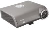
Sharp DT 400 - HDTV- DLP Projector Manual
 |
UPC - 074000364332
View all Sharp DT 400 manuals
Add to My Manuals
Save this manual to your list of manuals |
Sharp DT 400 manual content summary:
- Sharp DT 400 | DT-400 Operation Manual - Page 1
on page 5. Model No.: DT-400 Serial No.: There are two important reasons for prompt warranty registration of your new SHARP Projector, using the REGISTRATION CARD packed with the projector. 1. WARRANTY This is to assure that you immediately receive the full benefit of the parts, service and labor - Sharp DT 400 | DT-400 Operation Manual - Page 2
if you are located in the United States of America, the Electronic Industries Alliance: www.eiae.org . Declaration of Conformity SHARP PROJECTOR, MODEL DT-400 This device complies with Part 15 of the FCC rules. Operation is subject to the following conditions: (1) This device may not cause harmful - Sharp DT 400 | DT-400 Operation Manual - Page 3
. Therefore you may not copy, modify, adapt, translate, distribute, reverse engineer, reverse assemble or discompile the contents thereof. This SHARP projector uses a DMD panel. This very sophisticated panel contains 921,600 pixels micromirrors. As with any high technology electronic equipment such - Sharp DT 400 | DT-400 Operation Manual - Page 4
Lamp 56 Lamp 56 Caution Concerning the Lamp 56 Replacing the Lamp 56 Removing and Installing the Lamp Unit 57 Resetting the Lamp Timer 58 Connecting Pin Assignments 59 Computer Compatibility Chart 60 Troubleshooting 61 Service Information (For the U.S 61 -4 Setup Setting Up the Projector - Sharp DT 400 | DT-400 Operation Manual - Page 5
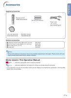
Lamp unit AN-C3CP AN-A1DV AN-C3DV AN-K2LP Note • Some of the optional accessories may not be available depending on the region. Please check with your nearest Sharp Authorized Service Center or Dealer. Marks Used in This Operation Manual Info ........Indicates safeguards when using the projector - Sharp DT 400 | DT-400 Operation Manual - Page 6
, ensure the service technician has used replacement parts specified by the manufacturer or have the same characteristics as the original part. Unauthorized substitutions may result in fire, electric shock, or other hazards. 20. Safety Check Upon completion of any service or repairs to this product - Sharp DT 400 | DT-400 Operation Manual - Page 7
safeguards when setting up your projector. Caution concerning the lamp unit ■ Potential hazard of glass particles if lamp ruptures. In case of lamp rupture, contact your nearest Sharp Authorized Service Center or Dealer for a replacement. See "Replacing the Lamp" on page 56. Caution concerning - Sharp DT 400 | DT-400 Operation Manual - Page 8
projector starts to overheat due to setup problems or blockage of the air vents, " " and " " will illuminate in the lower left corner of the picture. If the temperature continues to rise, the lamp will turn automatically controlled. The sound of the fan may change during projector operation - Sharp DT 400 | DT-400 Operation Manual - Page 9
Part Names and Functions Numbers in refer to the main pages in this operation manual where the topic is explained. Projector Top View ON button 28 Turn the power on. STANDBY button 29 Put the projector View Remote control sensor 13 Front adjustment foot 31 (on the bottom of the projector) HEIGHT - Sharp DT 400 | DT-400 Operation Manual - Page 10
Part Names and Functions About the Indicators on the Projector Power indicator Red on ... Normal (Standby) Green on ... Normal (Power on) Lamp indicator Green on ... Normal Green blinks ... The lamp is warming up or shutting down. Red on ... The lamp has been shut down abnormally or needs to be - Sharp DT 400 | DT-400 Operation Manual - Page 11
This is normal operation and does not indicate a malfunction. 13 Remote control sensor 11 Kensington Security Standard connector 28 AC socket Connect the supplied Power cord. Using the Kensington Lock • This projector has a Kensington Security Standard connector for use with a Kensington MicroSaver - Sharp DT 400 | DT-400 Operation Manual - Page 12
Part Names and Functions Numbers in refer to the main pages in this operation manual where the topic is explained. Remote Control STANDBY button 29 Put the projector into standby mode. KEYSTONE button 32 Enter the Keystone Correction mode. ENTER button 39 Set items selected or adjusted on the menu - Sharp DT 400 | DT-400 Operation Manual - Page 13
remote control: • Ensure not to drop, expose to moisture or high temperature. • The remote control may malfunction under a fluorescent lamp. In this case, move the projector away from the fluorescent lamp projector may run down in a short period, depending on how they are kept. Ensure to replace - Sharp DT 400 | DT-400 Operation Manual - Page 14
the power cord into the AC socket of the projector Connect the audio output terminal of the video equipment to the audio input terminal of the audio equipment using an audio cable. Pages 21-27 3. Remove the lens cap and turn the projector on On the projector On the remote control Page 27 -14 - Sharp DT 400 | DT-400 Operation Manual - Page 15
on the remote control. On the On the remote " On-screen Display projector control • When pressing on the projector, input mode switches in order of : INPUT 1 INPUT 2 INPUT 3 INPUT 4 INPUT 5 DIGITAL • When using the remote control, press ///// to switch the INPUT mode. Page 29 5. Turn the - Sharp DT 400 | DT-400 Operation Manual - Page 16
. Light falling directly on the screen washes out the colors, making viewing difficult. Close the curtains and dim the lights when setting up the projector in a sunny or bright room. Standard Setup (Front Projection) ■ Place the projector at the required distance from the screen according to the - Sharp DT 400 | DT-400 Operation Manual - Page 17
projected onto the screen at the optimum size by referring to the table below. Use the values in the table as a reference when installing the projector. Side View Screen H Lens center L When using a wide screen (16:9): In case of displaying the 16:9 picture on the whole of the 16:9 screen. Diag - Sharp DT 400 | DT-400 Operation Manual - Page 18
light does not shine into the eyes of the audience. Ceiling-mount Setup ■ It is recommended that you use the optional Sharp ceiling-mount bracket for this installation. ■ Before mounting the projector, contact your nearest Sharp Authorized Service Center or Dealer to obtain the recommended ceiling - Sharp DT 400 | DT-400 Operation Manual - Page 19
Connections INPUT Terminals and Connectable Main Equipment INPUT 5/DIGITAL terminal Connecting video equipment with component output terminal (DVD player, DTV decoder, DVD recorder with hard disc, etc.). (See pages 22, 23.) Connecting the computer. (See pages 25, 26.) INPUT 1, 2 terminal - Sharp DT 400 | DT-400 Operation Manual - Page 20
• For more details of connection and cables, refer to the opeation manual of the connecting equipment. • You may need other cables or connectors output terminal Component cable (commercially available) Terminal on the projector INPUT 1, 2 Terminal for using the dedicated cable Dedicated cable - Sharp DT 400 | DT-400 Operation Manual - Page 21
connecting, ensure to unplug the power cord of the projector from the AC outlet and turn off the devices to be connected. After making all connections, turn on the projector and then the other devices. Ensure to read the operation manuals of the devices to be connected before making connections - Sharp DT 400 | DT-400 Operation Manual - Page 22
connecting the component video equipment to the DVI input terminal on the projector (INPUT 5) • Before connecting the cable, switch the digital " for "Signal Type" on the OSD menu or press control. (See page 48.) on the remote When connecting the video equipment with RGB output terminal (INPUT - Sharp DT 400 | DT-400 Operation Manual - Page 23
When connecting the video equipment with DVI output terminal (DIGITAL INPUT) • Before connecting the cable, switch the digital input type switch to "VIDEO". DVI output terminal DVD Player,etc. DIGITAL terminal 1 Switch to "VIDEO" 2 DVI cable (sold separately: AN-C3DV) 3 Note • Select DIGITAL - Sharp DT 400 | DT-400 Operation Manual - Page 24
Connecting to Video Equipment When connecting video equipment with S-video output terminal (INPUT 3) S-video output terminal DVD Player,etc. 2 INPUT 3 terminal 1 S-video cable (commercially available) When connecting video equipment with video output terminal (INPUT 4) Video output terminal - Sharp DT 400 | DT-400 Operation Manual - Page 25
the last device to be turned on after all the projector to a computer in this way, select "RGB" for "Signal Type" on the OSD menu or press on the remote control. (See page 48.) • A Macintosh adaptor may be required for use with some Macintosh computers. Contact your nearest Sharp Authorized Service - Sharp DT 400 | DT-400 Operation Manual - Page 26
, allowing for quick and easy setup. ■ Before using the "Plug and Play" function, ensure to turn on the projector first and the connected computer last. Note • The DDC "Plug and Play" function of this projector operates only when used in conjunction with a VESA DDC compatible computer. -26 - Sharp DT 400 | DT-400 Operation Manual - Page 27
(6' (1.8 m)) Turning the Projector On Before performing the steps in this section, connect any equipment that you use with the projector. (See pages 19-26.) Remove the lens cap and press on the projector or on the remote control. • The power indicator illuminates green. • After the lamp indicator - Sharp DT 400 | DT-400 Operation Manual - Page 28
Turning the Projector On/Off Turning the Power Off (Put- ting the Projector into Standby Mode) 1 Press on the projector or on the remote control, then press that button again while the confir- mation message is displayed, to put the projector into standby mode. ▼On-screen Display STANDBY - Sharp DT 400 | DT-400 Operation Manual - Page 29
Switching the INPUT Mode Select the appropriate input mode for the connected equipment. Press , , , , or on the remote control to select the input mode. • When pressing on the projector, input mode switches in order of : INPUT 1 INPUT 2 INPUT 3 DIGITAL INPUT 5 INPUT 4 Note • When no signal is - Sharp DT 400 | DT-400 Operation Manual - Page 30
the Focus 1 Press on the remote control. 2 Press \ or | on the remote con- trol to adjust the focus. Note • You can also adjust the focus by using and \ or | on the projector. Adjusting the Projected Image Size 1 Press on the remote control. 2 Press ' or " on the remote con- trol to adjust the zoom - Sharp DT 400 | DT-400 Operation Manual - Page 31
its height. 2 Remove your hands from the HEIGHT ADJUST button of the projector after its height has been finely adjusted. HEIGHT ADJUST button Front adjustment foot 3 Finely adjust the height and in- clination by turning the rear ad- justment feet. Note • When adjusting the projected image - Sharp DT 400 | DT-400 Operation Manual - Page 32
1 Press on the remote control to enter the Keystone Correction mode. 2 Press '/" to select"H Keystone" or "V Keystone". Selectable items Description H Keystone Horizontally adjusts the keystone settings. V Keystone Vertically adjusts the keystone settings. Reset - Sharp DT 400 | DT-400 Operation Manual - Page 33
be projected onto the screen by referring to "Screen Size and Projection Distance" on page 17. 3 Align the edge of the screen closest to the projector with the test pattern by adjusting the zoom and the adjsuter. (See pages 30 and 31.) ZOOM FOCUS ZOOM/FOCUS END Align : Screen area Note - Sharp DT 400 | DT-400 Operation Manual - Page 34
Press on the remote control. • Each time is pressed, the picture mode changes as shown on the next page. • To return to the standard image ("STRETCH"), press while "RESIZE" is displayed on the screen. • You can also change the picture display mode by pressing on the projector - Sharp DT 400 | DT-400 Operation Manual - Page 35
Input signal STRETCH Output screen image SIDE BAR SMART STRETCH CINEMA ZOOM 4:3 aspect ratio 480I 480P 576I 576P NTSC PAL SECAM Letterbox Squeeze 16:9 aspect ratio 540P 1080I 16:9 aspect ratio 720P 16:9 aspect ratio VGA SVGA XGA 4:3 aspect ratio Note • "SMART STRETCH" cannot be selected - Sharp DT 400 | DT-400 Operation Manual - Page 36
that can be set in the projector. "Picture" menu Example: Screen for INPUT 1 mode Example: Screen for INPUT 5 (RGB) mode Main Menu Picture Page 42 Contrast -30 +30 Bright Color Tint Sharp -30 +30 -30 +30 *1 -30 +30 *1 -30 +30 *1 Red -30 +30 Blue -30 +30 Reset Page 42 CLR Temp Page 42 - Sharp DT 400 | DT-400 Operation Manual - Page 37
4 mode "Language" menu "PRJ Mode" menu Main Menu Options Page 47 Lamp Timer (Life) Page 47 OSD Display [ON/OFF] Page 47 *1 Video System Menu Position Page 50 Center Upper Right Lower Right Upper Left Lower Left Menu Color [Opaque/Translucent] Page 51 *1: Item when selecting INPUT 3 or INPUT - Sharp DT 400 | DT-400 Operation Manual - Page 38
('/"/\/|) ENTER button MENU button UNDO button Menu Selections (Adjustments) • This operation can also be performed by using the buttons on the projector. 1 Press . • The "Picture" menu screen for the selected input mode is displayed. 2 Press | or \ to display the other menu screens. • The - Sharp DT 400 | DT-400 Operation Manual - Page 39
viewing it Press . • The selected single adjustment item (e.g. "Bright") appears on the lower part of the screen. • When pressing ' or ", the next item will be displayed. (e.g. "Bright" is replaced with "Color" by pressing ".) Single adjustment items Note • Press to return to the previous screen - Sharp DT 400 | DT-400 Operation Manual - Page 40
('/"/\/|) ENTER button MENU button UNDO button Menu Selections (Settings) • This operation can also be performed by using the buttons on the projector. 1 Press . • The "Picture" menu screen for the selected input mode is displayed. Example: "Picture" menu screen for INPUT 1 mode Menu icons - Sharp DT 400 | DT-400 Operation Manual - Page 41
3 Press ' or " to select the item you want to set, and then press | to display the sub menu. • The selected item is highlighted. (Example: Selecting "Menu Position") Note • Press or \ to return to the previous screen. • For some items, press \ or | to select the icon using " ". 4 Press ' or " to - Sharp DT 400 | DT-400 Operation Manual - Page 42
Adjustment ("Picture" menu) You can adjust the projector's picture to your preferences using the "Picture" weaker blue For stronger blue Note • "Color", "Tint" and "Sharp" do not appear for RGB input in INPUT 5 mode. • To reset all adjustment items, select "Reset" on the "Picture" menu screen and - Sharp DT 400 | DT-400 Operation Manual - Page 43
Items Description (ON) For emphasising the bright portions of images (OFF) For disabling "Bright Boost" 2 Press ' or " to fine adjust the color temperature. • With the lower value selected, the projected image becomes less brightness. With the higher value selected, the projected image becomes - Sharp DT 400 | DT-400 Operation Manual - Page 44
Contrast Mode This function changes the brightness and contrast of the projected image. It can be operated using the IRIS button on the remote control. Menu operation Page 40 Example: "Picture" menu screen for INPUT 1 mode Select "Picture Mode" on the "Picture" menu and the memory location where - Sharp DT 400 | DT-400 Operation Manual - Page 45
Auto Sync" on the "Fine Sync" menu to " " (ON) or pressing on the re- mote control. See page 46. • "Clock", "Phase", "H-Pos" and "V-Pos" cannot be used in the may be changed according to the input signal. • To reset all adjustment items, select "Reset" and press . Note • If your computer displays - Sharp DT 400 | DT-400 Operation Manual - Page 46
also performed by pressing on the remote control. • The Auto Sync adjustment may take some time to complete, depending on the image of the computer connected to the projector. • When the optimum image cannot be achieved with Auto Sync adjustment, use manual adjustments. (See page 45.) • "Auto Sync - Sharp DT 400 | DT-400 Operation Manual - Page 47
projector. Checking the Lamp Life Status You can confirm the cumulative lamp usage time and the remaining lamp life (percentage). Menu operation Page 40 Example: "Options" menu screen for INPUT 1 mode Setting On-screen Display This function allows you to turn - Sharp DT 400 | DT-400 Operation Manual - Page 48
RGB Set when RGB signals are received. Component Set when Component signals are received. Note • You can also select "Signal Type" using on the remote control (only INPUT 5). Note • The video signal can only be set in INPUT 3, INPUT 4 mode. • "Auto" cannot be set for PAL-M and PAL-N input - Sharp DT 400 | DT-400 Operation Manual - Page 49
to select the image displayed when no signal is being sent to the projector. Menu operation Page 40 Example: "Options" menu screen for INPUT 1 Description of Eco Mode Selectable items Brightness Power consumption (When using AC 100V) Lamp life (Eco mode) 85% 315 W Approx. 3,000 hours 100% ( - Sharp DT 400 | DT-400 Operation Manual - Page 50
. (OFF) The Auto Power Off function will be disabled. Note • When the Auto Power Off function is set to " " (ON), 5 minutes before the projector enters the standby mode, the message "Enter STANDBY mode in X min." will appear on the screen to indicate the remaining minutes. Description of Menu - Sharp DT 400 | DT-400 Operation Manual - Page 51
Menu operation Page 40 Example: "Options" menu screen for INPUT 1 mode Description of Menu Colors Selectable Items Description (Opaque) The menu is displayed opaquely. The menu is displayed (Translucent) translucently. The part of the menu on the image becomes transparent. Useful Features -51 - Sharp DT 400 | DT-400 Operation Manual - Page 52
projector is equipped with a reverse/invert image function that allows you to reverse or invert the projected image for various applications. Menu operation Page 40 Example: "PRJ Mode" menu screen 1 Press on the remote control is used for the reversed image and ceiling-mount setups. (See page 18.) - Sharp DT 400 | DT-400 Operation Manual - Page 53
. Make sure to test on a small, inconspicuous area on the projector before use. Info • If you want to clean the air vents of projector, ensure to press on the projector or on the remote control and put the projector into standby mode. After the cooling fan has stopped, unplug the power - Sharp DT 400 | DT-400 Operation Manual - Page 54
change to " " (red), the lamp will automatically turn off and then the projector will automatically enter the standby mode. At this time, the lamp indicator will illuminate in red. ■ If you try to turn on the projector a fourth time without replacing the lamp, the projector will not turn on. -54 - Sharp DT 400 | DT-400 Operation Manual - Page 55
it again. • Carefully replace the lamp. (See • Remaining lamp life page 57.) becomes 5% or less. • Take the projector to your nearest Sharp Authorized Service Center • Burnt-out lamp • Lamp circuit failure or Dealer for repair. • Please exercise care when replacing the lamp. Info • If the - Sharp DT 400 | DT-400 Operation Manual - Page 56
the instructions described in this section. *If you wish, you may have the lamp replaced at your nearest Sharp Authorized Service Center or Dealer. * If the new lamp does not light after replacement, take your projector to the nearest Sharp Authorized Service Center or Dealer for repair. -56 - Sharp DT 400 | DT-400 Operation Manual - Page 57
on the remote control to put the projector into standby mode. • Wait until the cooling fan stops. 2 Disconnect the power cord. • Unplug the power cord from the AC socket. • Leave the lamp until it has fully cooled down (about 1 hour). 3 Remove the lamp unit cover. • Turn the projector over. Loosen - Sharp DT 400 | DT-400 Operation Manual - Page 58
service screw to secure the lamp unit cover. Info • If the lamp unit and lamp unit cover are not correctly installed, the power will not turn on, even if the power cord is connected to the projector. Resetting the Lamp Timer Reset the lamp timer after replacing the lamp. Info • Make sure to reset - Sharp DT 400 | DT-400 Operation Manual - Page 59
Connecting Pin Assignments DVI-I (INPUT 5) port : 29 pin connector 9 ~ 16 1 2 7 8 17 24 18 23 • DVI Digital INPUT Pin No. Signal Pin No. Signal 1 T.M.D.S data 2- 16 Hot plug detection 2 T.M.D.S data 2+ 17 T.M.D.S data 0- 3 T.M.D.S data 2 shield 18 T.M.D.S data 0+ 4 Not connected C1 - Sharp DT 400 | DT-400 Operation Manual - Page 60
19" Resolution 640 × 350 720 × 350 640 × 400 VGA 720 × 400 640 × 480 SVGA 800 × 600 XGA 1,024 × Support Display Upscale Intelligent Compression Upscale Intelligent Compression Note • This projector can be found in your notebook computer's operation manual. DTV Signal 480I 480P 540P 576I 576P - Sharp DT 400 | DT-400 Operation Manual - Page 61
Troubleshooting Problem No picture Color is faded or poor. Check • Projector power cord is not plugged into the wall outlet. • Power to the external connected devices is off. • The selected input mode is wrong. • Cables are incorrectly connected to the rear panel of the projector. • External - Sharp DT 400 | DT-400 Operation Manual - Page 62
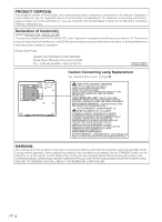
Replacement parts Lamp unit (Lamp/cage module) (AN-K2LP), Remote control (RRMCGA334WJSA), AA size batteries, Power cord (QACCDA007WJPZ), Lens cap (PCAPHA021WJSA), Operation manual (TINS-B532WJZZ) As a part of policy of continuous improvement, SHARP reserves the right to make design and specification - Sharp DT 400 | DT-400 Operation Manual - Page 63
Dimensions Units: inches (mm) Side View Rear View Top View Side View 1/16 (1.5) 11 7/64 (282) 9/64 (3.25) Front View Bottom View 9/16 (14) 13/64 (5) 3 33/64 (89) 12 7/32 (310) 2 11/64 (55.05) 1 59/64 (48.5) 2 3/16 (55.5) 5 7/64 (129.5) 3 15/16 (99.95) 5 7/64 (129.5) 1 5/32 1 7/32 M4 - Sharp DT 400 | DT-400 Operation Manual - Page 64
used to adjust vertical noise when clock level is incorrect. CLR Temp (Color temperature) Function that can be used to adjust the color temperature to suit the type of image input to the projector. Decrease the color temperature to create warmer, reddish images for natural flesh tones, or increase - Sharp DT 400 | DT-400 Operation Manual - Page 65
Keystone Correction 32 L Lamp 56 Lamp indicator 54 Lamp Timer (Life 47 Language 52 Lens cap 9 M MENU button 38 Menu Color 51 Menu Position 50 adjustment feet 31 Red 42 Remote control 12 Remote control sensor 13 Replacing the lamp 56 RESIZE button 34 S Sharp 42 Signal Info 46 Signal - Sharp DT 400 | DT-400 Operation Manual - Page 66
Coverage (if any): Where to Obtain Service: What to do to Obtain Service: DT-400 Projector (Be sure to have this information available when you need service for your Product.) One (1) year parts and labor from date of purchase except for the Projector Lamp for which the warranty period is ninety - Sharp DT 400 | DT-400 Operation Manual - Page 67
specified or approved by Sharp, including but not limited to head cleaning tapes and chemical cleaning agents. (d) Any replacement of accessories, glassware, consumable or peripheral items required through normal use of the product including but not limited to earphones, remote controls, AC adapters
-
 1
1 -
 2
2 -
 3
3 -
 4
4 -
 5
5 -
 6
6 -
 7
7 -
8
-
9
-
10
-
11
-
12
-
13
-
14
-
15
-
16
-
17
-
18
-
19
-
20
-
21
-
22
-
23
-
24
-
25
-
26
-
27
-
28
-
29
-
30
-
31
-
32
-
33
-
34
-
35
-
36
-
37
-
38
-
39
-
40
-
41
-
42
-
43
-
44
-
45
-
46
-
47
-
48
-
49
-
50
-
51
-
52
-
53
-
54
-
55
-
56
-
57
-
58
-
59
-
60
-
61
-
62
-
63
-
64
-
65
-
66
-
67
 |
 |
-1
ENGLISH
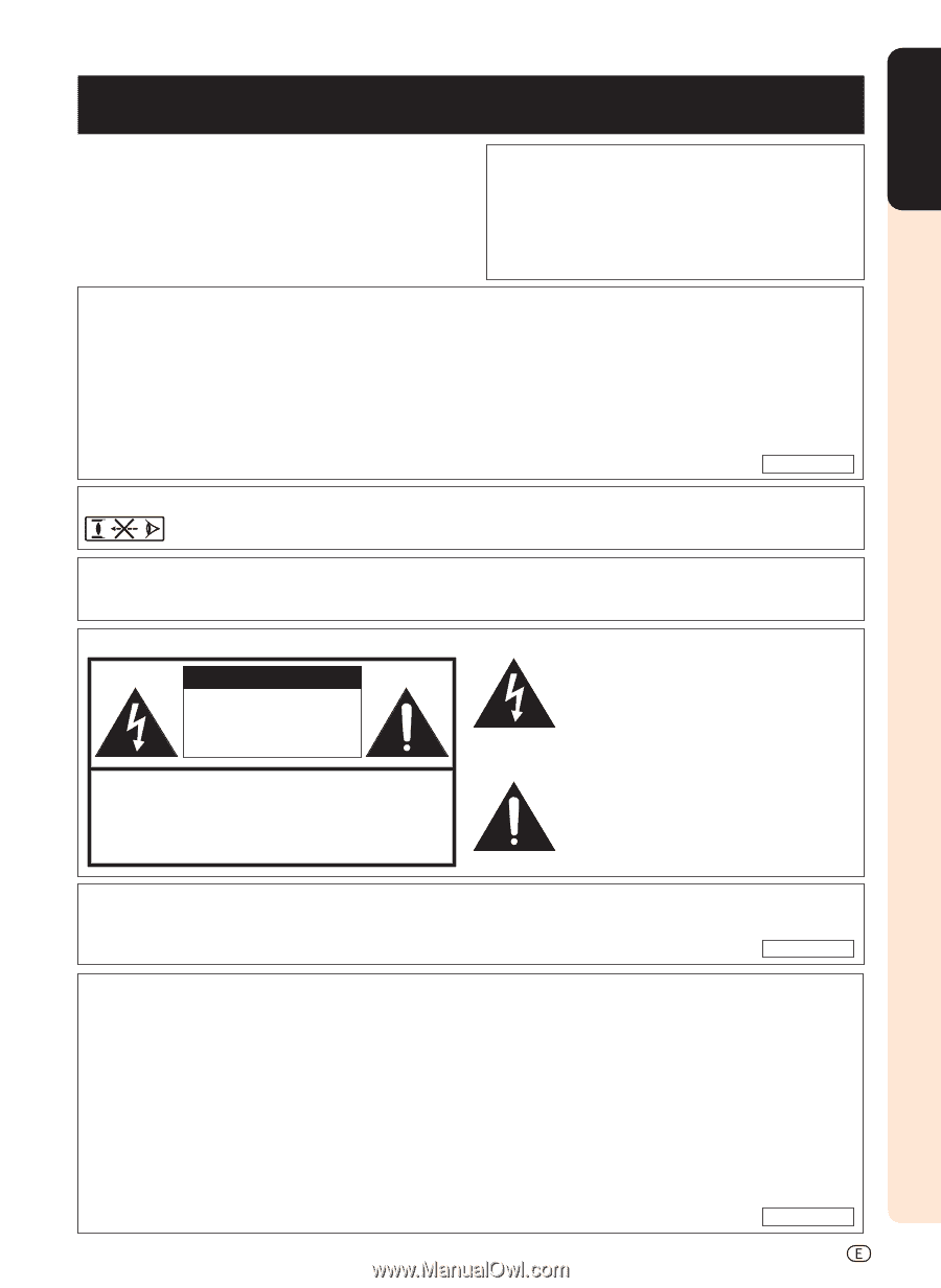
Before using the projector, please read this operation manual carefully.
WARNING:
High brightness light source. Do not stare into the beam of light, or view directly. Be especially
careful that children do not stare directly into the beam of light.
WARNING:
To reduce the risk of fire or electric shock, do not expose this product to
rain or moisture.
CAUTION: TO REDUCE THE RISK OF ELECTRIC SHOCK,
DO NOT REMOVE COVER.
NO USER-SERVICEABLE PARTS EXCEPT LAMP UNIT.
REFER SERVICING TO QUALIFIED SERVICE
PERSONNEL.
The lightning flash with arrowhead symbol,
within an equilateral triangle, is intended to
alert the user to the presence of uninsulated
“dangerous voltage” within the product’s
enclosure that may be of sufficient magnitude
to constitute a risk or electric shock to
persons.
The exclamation point within a triangle is
intended to alert the user to the presence of
important operating and maintenance
(servicing) instructions in the literature
accompanying the product.
Introduction
CAUTION
RISK OF ELECTRIC SHOCK.
DO NOT REMOVE SCREWS
EXCEPT SPECIFIED USER
SERVICE SCREW.
See bottom of projector.
IMPORTANT
For your assistance in reporting the loss or theft of your
Projector, please record the Serial Number located on
the bottom of the projector and retain this information.
Before recycling the packaging, please ensure that you
have checked the contents of the carton thoroughly
against the list of “Supplied accessories” on page
5
.
Model No.: DT-400
Serial No.:
There are two important reasons for prompt warranty registration of your new SHARP Projector, using
the REGISTRATION CARD packed with the projector.
1. WARRANTY
This is to assure that you immediately receive the full benefit of the parts, service and labor
warranty applicable to your purchase.
2.
CONSUMER PRODUCT SAFETY ACT
To ensure that you will promptly receive any safety notification of inspection, modification, or
recall that SHARP may be required to give under the 1972 Consumer Product Safety Act, PLEASE
READ CAREFULLY THE IMPORTANT “LIMITED WARRANTY” CLAUSE.
U.S.A. ONLY
WARNING:
FCC Regulations state that any unauthorized changes or modifications to this equipment not
expressly approved by the manufacturer could void the user’s authority to operate this equip-
ment.
U.S.A. ONLY
INFORMATION
This equipment has been tested and found to comply with the limits for a Class B digital device, pursuant to Part
15 of the FCC Rules. These limits are designed to provide reasonable protection against harmful interference in a
residential installation. This equipment generates, uses, and can radiate radio frequency energy and, if not installed
and used in accordance with the operation manual, may cause harmful interference to radio communications.
However, there is no guarantee that interference will not occur in a particular installation. If this equipment does
cause harmful interference to radio or television reception, which can be determined by turning the equipment off
and on, the user is encouraged to try to correct the interference by one or more of the following measures:
• Reorient or relocate the receiving antenna.
• Increase the separation between the equipment and the receiver.
• Connect the equipment into an outlet on a circuit different from that to which the receiver is connected.
• Consult the dealer or an experienced radio/TV technician for help.
U.S.A. ONLY