Sony CCD-FX520 Primary User Manual - Page 22
Identifying, Parts
 |
View all Sony CCD-FX520 manuals
Add to My Manuals
Save this manual to your list of manuals |
Page 22 highlights
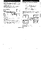
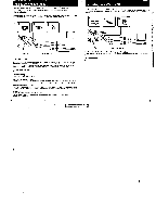
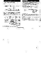
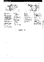
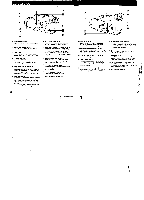
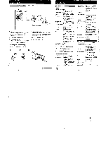
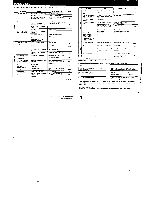
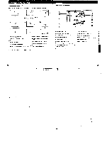
Identifying the Parts 6 7 8 2 9 3 4 5 t- POWER switch (p.11) CAMERA, for camera recording VTR for playing back or editing tape OFF power oft REMOTE It (LANG) control jack Connect the LANG It connecting cable of a wir. remote control unit such as editing controller. In this case, set the ■ REMOTE COMMANDER switch to OFF 1p 24) tt (LANG) stands for Local Application Control Bus System. The It control jack Is used for controlling the tape transport of video equipment end peripherals connected to il. This jack has the same function as the connectors indicated as CONTROL L or REMOTE. (earphone) jack (minijack) (p. 21) Connect an earphone mot supplied) to monitor the sound while viewing the playback Or the recording picture. A/ START/STOP button (p. 17) To start recording, press after setting the POWER switch to CAMERA and turning STANDBY up. To stop recording momentarily, press at again. STANDBY switch (p. 11) To set the camcorder to Standby mode a'ecording standby model. am it up. To moo recording or to prevent from accidentally reseeding and wearing down the battery. set it ▪ EDITSEARCH (and W recording review) button (p. 21) Press .1 to check the recorded scene in the viewfinder in Standby mode o side to view the playback picture forward - ode to view the playback picture in reverse T Power zoom button (p. 19) Press it to change the size of the sullen in tee scene T side for telephoto Isubtect appears closer, W ode for wide-angle (subject appears lurlher away) An Built-in Microphone T EJECT (cassette e)ect) button Ita. 15) While pressing the blue button. slide It to insert or elect a cassette. ▪ holder (p. 15) in Lithium battery holder (p.10) Insert a lithium battery here to activate the desk. ▪ Grip strap (p. 16) Put your hand thorugh the grip strap t0 hold the CaRIcorder. Adtust the length of the strap so that your thumb can easily touch START STOP 42 13 15 or 16 • 0 21 14 its Tape transport buttons (p. 23) ▪ STOP .414 REW revand) > PLAY (playback) • FF Mast forward) II PAUSE • REC (wording) These buttons will function in VTR mode. iii Lens cap (p. 17) Attach it to the lens when not using the camera. Put It on the grip strata while camera recording. isl MIC jack )p.44) Connect an optional external microphone {monaural) This tack also accepts a -plug-inPOwer microphone. It the microphone haS aao plugs. connect the DC IN plug to the RFU DC OUT Jed( on the camcorder. A Remote control sensor (p. 46) Am the Remote Commander here for remote control. W. EMT switch (p.34) Set am the dmec0on of the arrow when oolong onto another tape. A OUT/IN (video and audio input/output) selector (p. 22, 34, 35) Set I to OUT when playing back the tape Set It to IN when recording or editing from a TV or another VCR. is RFU DC OUT (RFU adaptor DC output) jack (p. 22) To view the recorded picture on the TV that has only an antenna input. connect the RFU adaptor here. LAI Hook for shoulder strap (p. 46) W. VIDEO/AUDIO leeks (p. 23) These lacks work as both input and output jacks by swactang the IN/OUT .lector on the camcorder. To view the recorded picture On the TV or to word onto another tape, conned these jacks and the VIDEO/AUDIO input jacks on the TV or VCR using en kV connecting cable not supplied) To record from a TV en a VCR. connect these tacks and the VIDEO/ AUDIO output mcks on Me TV or VCR. 43
-
 1
1 -
2
-
3
-
4
-
5
-
6
-
7
-
8
-
9
-
10
-
11
-
12
-
13
-
14
-
15
-
16
-
 17
17 -
 18
18 -
 19
19 -
 20
20 -
 21
21 -
 22
22 -
 23
23 -
 24
24 -
 25
25 -
 26
26
 |
 |
