Sony DCR-HC26 Operating Guide - Page 49
Dubbing/Editing, Dubbing to VCR/DVD device, etc - cable
 |
UPC - 027242688711
View all Sony DCR-HC26 manuals
Add to My Manuals
Save this manual to your list of manuals |
Page 49 highlights
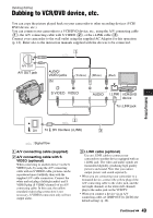
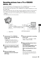
Dubbing/Editing Dubbing to VCR/DVD device, etc. You can copy the picture played back on your camcorder to other recording devices (VCR/ DVD device, etc.). You can connect your camcorder to a VCR/DVD device, etc., using the A/V connecting cable (1), the A/V connecting cable with S VIDEO (2), or the i.LINK cable (3). Connect your camcorder to the wall outlet using the supplied AC Adaptor for this operation (p. 12). Refer also to the instruction manuals supplied with the devices to be connected. 1 A/V OUT A/V OUT jack AUDIO/ VIDEO jacks (Yellow) (White) (Red) Dubbing/Editing VCR/DVD device To i.LINK jack 2 DV To DV Interface (i.LINK) 3 : Signal flow A A/V connecting cable (supplied) B A/V connecting cable with S VIDEO (optional) When connecting to another device via the S VIDEO jack, by using the A/V connecting cable with an S VIDEO cable, pictures can be reproduced more faithfully than with the supplied A/V cable connection. Connect the white and red plugs (left/right audio) and S VIDEO plug (S VIDEO channel) of an A/V connecting cable. In this case, the yellow (standard video) plug connection is not necessary. S VIDEO connection only will not output audio. C i.LINK cable (optional) Use an i.LINK cable to connect your camcorder to another device equipped with an i.LINK jack. The video and audio signals are transmitted digitally, producing high quality pictures and sound. Note that you cannot output picture and sound separately. • When you are connecting your camcorder to a monaural device, connect the yellow plug of the A/V connecting cable to the video jack, and the red (right channel) or the white (left channel) plug to the audio jack on the VCR/TV. • When you connect a device via an A/V connecting cable, set [DISP OUT] to [LCD] (the default setting) (p. 48). Continued , 49
-
 1
1 -
2
-
3
-
4
-
5
-
6
-
7
-
8
-
9
-
10
-
11
-
12
-
13
-
14
-
15
-
16
-
17
-
18
-
19
-
20
-
21
-
22
-
23
-
24
-
25
-
26
-
27
-
28
-
29
-
30
-
31
-
32
-
33
-
34
-
35
-
36
-
37
-
38
-
39
-
40
-
41
-
42
-
43
-
 44
44 -
 45
45 -
 46
46 -
 47
47 -
 48
48 -
 49
49 -
 50
50 -
 51
51 -
 52
52 -
 53
53 -
 54
54 -
55
-
56
-
57
-
58
-
59
-
60
-
61
-
62
-
63
-
64
-
65
-
66
-
67
-
68
-
69
-
70
-
71
-
72
-
73
-
74
-
75
-
76
-
77
-
78
-
79
-
80
-
81
-
82
-
83
-
84
-
85
-
86
-
87
-
88
-
89
-
90
-
91
-
92
 |
 |
