TP-Link EAP115 EAP115EU V1 User Guide - Page 11
Panel Layout - wall firmware
 |
View all TP-Link EAP115 manuals
Add to My Manuals
Save this manual to your list of manuals |
Page 11 highlights
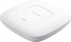
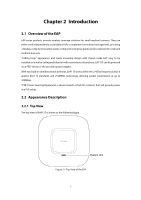
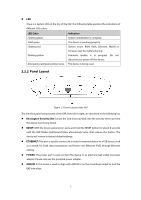
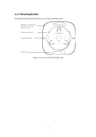
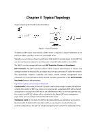
LED There is a System LED on the top of the EAP. The following table explains the indications of different LED colors. LED Color Flashing green Solid green Flashing red Flashing yellow Alternating red/green/yellow twice Indication System initialization is complete. The device is working properly. System errors. RAM, flash, Ethernet, WLAN or firmware may be malfunctioning. Firmware update is in progress. Do not disconnect or power off the device. The device is being reset. 2.2.2 Panel Layout Figure 2-2 Panel Layout of the EAP The interface panel components of the EAP, from left to right, are described in the following list: Kensington Security Slot: Secure the lock (not provided) into the security slot to prevent the device from being stolen. RESET: With the device powered on, press and hold the RESET button for about 8 seconds until the LED flashes Red/Green/Yellow alternatively twice, then release the button. The device will restore to factory default settings. ETHERNET: This port is used to connect to a router to transmit data or to a PSE device, such as a switch, for both data transmission and Power over Ethernet (PoE) through Ethernet cabling. POWER: The power port is used connect the device to an electrical wall outlet via power adapter. Please only use the provided power adapter. ARROW 1: This arrow is used to align with ARROW 2 on the mounting bracket to lock the EAP into place. 3
-
 1
1 -
2
-
3
-
4
-
5
-
 6
6 -
 7
7 -
 8
8 -
 9
9 -
 10
10 -
 11
11 -
 12
12 -
 13
13 -
 14
14 -
 15
15 -
 16
16 -
17
-
18
-
19
-
20
-
21
-
22
-
23
-
24
-
25
-
26
-
27
-
28
-
29
-
30
-
31
-
32
-
33
-
34
-
35
-
36
-
37
-
38
-
39
-
40
-
41
-
42
-
43
-
44
-
45
-
46
-
47
-
48
-
49
-
50
-
51
-
52
-
53
-
54
-
55
-
56
-
57
-
58
-
59
-
60
-
61
-
62
-
63
-
64
-
65
-
66
-
67
-
68
-
69
-
70
-
71
-
72
-
73
-
74
-
75
-
76
-
77
-
78
-
79
-
80
-
81
-
82
-
83
-
84
-
85
-
86
-
87
-
88
-
89
-
90
-
91
-
92
-
93
-
94
-
95
-
96
-
97
-
98
-
99
-
100
-
101
-
102
-
103
-
104
-
105
-
106
-
107
-
108
-
109
-
110
-
111
-
112
-
113
-
114
-
115
-
116
-
117
-
118
-
119
-
120
-
121
-
122
-
123
-
124
-
125
-
126
-
127
 |
 |
