TP-Link TL-SL2218 TL-SL2218 V1 User Guide
TP-Link TL-SL2218 Manual
 |
View all TP-Link TL-SL2218 manuals
Add to My Manuals
Save this manual to your list of manuals |
TP-Link TL-SL2218 manual content summary:
- TP-Link TL-SL2218 | TL-SL2218 V1 User Guide - Page 1
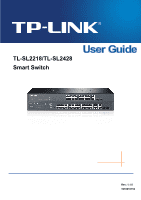
TL-SL2218/TL-SL2428 Smart Switch Rev: 1.1.0 1910010753 - TP-Link TL-SL2218 | TL-SL2218 V1 User Guide - Page 2
without permission from TP-LINK TECHNOLOGIES CO., LTD. Copyright © 2013 TP-LINK TECHNOLOGIES CO., LTD. All rights reserved. http://www.tp-link.com FCC and, if not installed and used in accordance with the instruction manual, may cause harmful interference to radio communications. Operation of this - TP-Link TL-SL2218 | TL-SL2218 V1 User Guide - Page 3
power source. z Don't disassemble the product, or make repairs yourself. You run the risk of electric shock and voiding the limited warranty. If you need service, please contact us. z Avoid water and wet locations. This product can be used in the following countries: AT BG BY CA CZ DE DK EE - TP-Link TL-SL2218 | TL-SL2218 V1 User Guide - Page 4
4.1.5 System IP...15 4.2 User Management ...16 4.2.1 User Table...16 4.2.2 User Config ...16 4.3 System Tools ...18 4.3.1 Config Restore 18 4.3.2 Config Backup 18 4.3.3 Firmware Upgrade 19 4.3.4 System Reboot 20 4.3.5 System Reset 20 4.4 Access Security ...20 Chapter 5 Switching ...23 5.1 Port - TP-Link TL-SL2218 | TL-SL2218 V1 User Guide - Page 5
5.1.3 Port Security ...27 5.1.4 Port Isolation ...29 5.2 LAG ...30 5.2.1 LAG Table ...30 5.2.2 Static LAG ...32 5.3 Traffic Monitor ...33 5.3.1 Traffic Summary 33 5.3.2 Traffic Statistics 34 5.4 MAC Address...36 5.4.1 Address Table 36 5.4.2 Static Address 38 5.4.3 Dynamic Address 39 5.4.4 - TP-Link TL-SL2218 | TL-SL2218 V1 User Guide - Page 6
8.3.1 IP-Range...86 8.3.2 Port Filter ...87 8.4 Packet Statistics...88 Chapter 9 QoS...90 9.1 DiffServ ...93 9.1.1 Port Priority ...93 9.1.2 802.1P Priority 94 9.1.3 DSCP Priority 95 9.1.4 Schedule Mode 97 9.2 Bandwidth Control ...98 9.2.1 Rate Limit...98 9.2.2 Storm Control 100 Chapter 10 SNMP - TP-Link TL-SL2218 | TL-SL2218 V1 User Guide - Page 7
11.2.1 Log Table ...121 11.2.2 Local Log ...122 11.2.3 Remote Log 122 11.2.4 Backup Log ...123 11.3 Device Diagnostics 124 11.3.1 Cable Test ...124 11.3.2 Loopback ...125 11.4 Network Diagnostics 126 11.4.1 Ping...126 11.4.2 Tracert...127 Appendix A: Specifications ...128 Appendix B: Configuring - TP-Link TL-SL2218 | TL-SL2218 V1 User Guide - Page 8
following items should be found in your box: ¾ One TL-SL2218 /TL-SL2428 Smart Switch ¾ One power cord ¾ Two mounting brackets and other fittings ¾ Installation Guide ¾ Resource CD for TL-SL2218 /TL-SL2428 Smart Switch, including: • This User Guide • Other Helpful Information Note: Make sure that the - TP-Link TL-SL2218 | TL-SL2218 V1 User Guide - Page 9
Chapter 1 About This Guide Chapter 2 Introduction Chapter 3 Login to the Switch Introduction Introduces the guide structure and conventions. Introduces the features, application and appearance of TL-SL2218/TL-SL2428 switch. Introduces how to log on to TL-SL2218/TL-SL2428 Web management page. 2 - TP-Link TL-SL2218 | TL-SL2218 V1 User Guide - Page 10
Web management page. This module is used to configure basic functions of the switch. Here mainly introduces: z Port: Configure the basic features for the port. z LAG: Configure Link , VLAN and multicast VLAN. z Multicast IP: Configure multicast IP table. z Multicast Filter: Configure multicast filter - TP-Link TL-SL2218 | TL-SL2218 V1 User Guide - Page 11
device are available. z Network Diagnostics: Test if the destination is reachable and the account of router hops from the switch to the destination. Lists the hardware specifications of the Switch. Introduces how to configure the PCs. Lists the glossary used in this manual. Return to CONTENTS 4 - TP-Link TL-SL2218 | TL-SL2218 V1 User Guide - Page 12
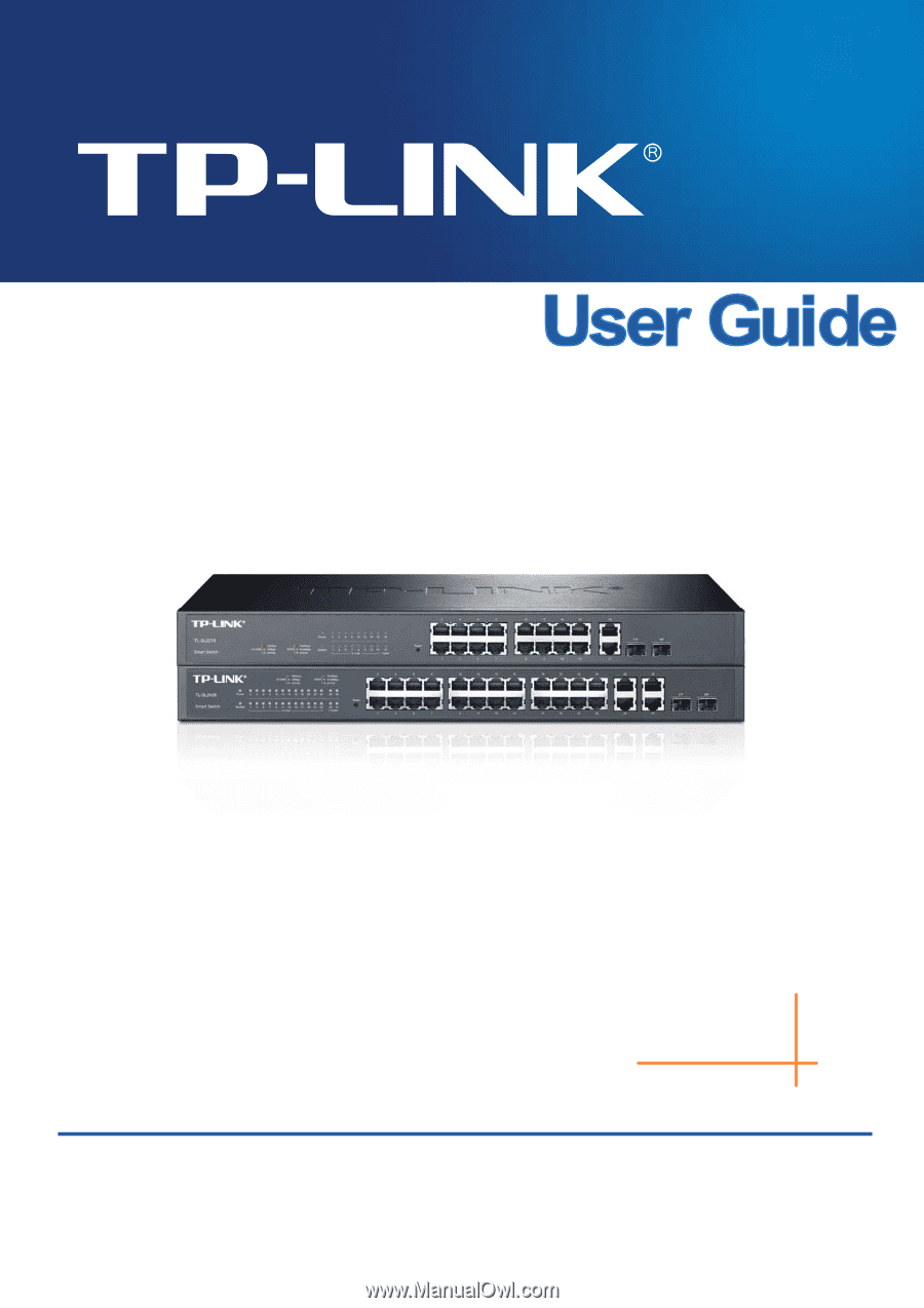
Thanks for choosing the TL-SL2218/TL-SL2428 Smart Switch! 2.1 Overview of the Switch Designed for workgroups and departments, TL-SL2218/TL-SL2428 from TP-LINK provides wire-speed performance and full set of layer 2 management features. They provide a variety of service features and multiple powerful - TP-Link TL-SL2218 | TL-SL2218 V1 User Guide - Page 13
TL-SL2218 The front panel of TL-SL2428 is shown as Figure 2-2. Figure 2-2 Front Panel of TL-SL2428 The following parts are located on the front panel of the Switch: ¾ Reset: With the Switch powered on, press Reset button for five seconds to reset the software setting to its factory default linked - TP-Link TL-SL2218 | TL-SL2218 V1 User Guide - Page 14
its corresponding Speed and Duplex mode on Switching→Port→Port Config page. For 100M module, please select 100MFD while select 1000MFD for gigabit module. By default, the Speed and Duplex mode of SFP port is 1000MFD. 2.3.2 Rear Panel The rear panel of TL-SL2218/TL-SL2428 features a power socket and - TP-Link TL-SL2218 | TL-SL2218 V1 User Guide - Page 15
the Enter key. Figure 3-1 Web-browser Tips: To log in to the Switch, the IP address of your PC should be set in the same subnet addresses of the Switch. The IP address is 192.168.0.x ("x" is any number from 2 to 254), Subnet Mask is 255.255.255.0. For the detailed instructions as to how to - TP-Link TL-SL2218 | TL-SL2218 V1 User Guide - Page 16
Figure 3-3 Main Setup-Menu Note: Clicking Apply can only make the new configurations effective before the switch is rebooted. If you want to keep the configurations effective even the switch is rebooted, please click Save Config. You are suggested to click Save Config before cutting off the power or - TP-Link TL-SL2218 | TL-SL2218 V1 User Guide - Page 17
System Summary, Device Description, System Time, Daylight Saving Time and System IP pages. 4.1.1 System Summary On this page you can view the port /100Mbps RJ45 ports, 4 10/100/1000Mbps RJ45 ports and 2 SFP ports of the switch. The ports labeled as 1-24 are 10/100Mbps ports; the ports labeled as 26- - TP-Link TL-SL2218 | TL-SL2218 V1 User Guide - Page 18
information of the port will be displayed. ¾ Port Info Figure 4-2 Port Information Port: Type: Speed: Status: Displays the port number of the switch. Displays the type of the port. Displays the maximum transmission speed of the port. Displays the connection status of the port. Click a port to - TP-Link TL-SL2218 | TL-SL2218 V1 User Guide - Page 19
the bandwidth utilization of sending packets on this port. 4.1.2 Device Description On this page you can configure the description of the switch, including device name, device location and system contact. Choose the menu System→System Info→Device Description to load the following page. Figure - TP-Link TL-SL2218 | TL-SL2218 V1 User Guide - Page 20
this option is selected, you can set the date and time manually. Synchronize with PC'S Clock: When this option is selected, the administrator PC's clock is utilized. Note: The system time will be restored to the default when the switch is restarted and you need to reconfigure the system time of - TP-Link TL-SL2218 | TL-SL2218 V1 User Guide - Page 21
Saving Time. Note: 1. When the DST is disabled, the predefined mode, recurring mode and date mode cannot be configured. 2. When the DST is enabled, the default daylight saving time is of European in predefined mode. 14 - TP-Link TL-SL2218 | TL-SL2218 V1 User Guide - Page 22
MAC Address: Displays MAC Address of the switch. IP Address Mode: Management VLAN: Select the mode to obtain IP Address for the switch. z Static IP: When this option is selected, you should enter IP Address, Subnet Mask and Default Gateway manually. z DHCP: When this option is selected, the - TP-Link TL-SL2218 | TL-SL2218 V1 User Guide - Page 23
not be configured. 7. By default, the default IP address is 192.168.0.1. 4.2 User Management User Management functions to configure the user name and password for users to log on to the Web management page with a certain access level so as to protect the settings of the switch from being randomly - TP-Link TL-SL2218 | TL-SL2218 V1 User Guide - Page 24
Figure 4-9 User Config The following entries are displayed on this screen: ¾ User Info User Name: Create a name for users' login. Access Level: User Status: Select the access level to login. z Admin: Admin can edit, modify and view all the settings of different functions. z Guest: Guest only - TP-Link TL-SL2218 | TL-SL2218 V1 User Guide - Page 25
4.3 System Tools The System Tools function, allowing you to manage the configuration file of the switch, can be implemented on Config Restore, Config Backup, Firmware Upgrade, System Reboot and System Reset pages. 4.3.1 Config Restore On this page you can upload a backup configuration file to - TP-Link TL-SL2218 | TL-SL2218 V1 User Guide - Page 26
. Please wait without any operation. 4.3.3 Firmware Upgrade The switch system can be upgraded via the Web management page. To upgrade the system is to get more functions and better performance. Go to http://www.tp-link.com to download the updated firmware. Choose the menu System→System Tools - TP-Link TL-SL2218 | TL-SL2218 V1 User Guide - Page 27
the switch to the default. All the settings will be cleared after the switch is default and all the settings will be cleared. 4.4 Access Security Access Security is configured to control the users logging on to the Web management page. On this page you can control the users logging on to the Web - TP-Link TL-SL2218 | TL-SL2218 V1 User Guide - Page 28
The following entries are displayed on this screen: ¾ Access Control Config Control Mode: IP Address&Mask Select the control mode for users to log on to the Web management page. z IP-based: Select this option to limit the IP-range of the users for login. z MAC-based: Select this option to limit - TP-Link TL-SL2218 | TL-SL2218 V1 User Guide - Page 29
¾ Session Config Session Timeout: ¾ Access User Number Number Control; Admin Number: Guest Number: If you do nothing with the Web management page within the timeout time, the system will log out automatically. If you want to reconfigure, please login again. Select Enable/Disable the Number - TP-Link TL-SL2218 | TL-SL2218 V1 User Guide - Page 30
it is in need. The parameters will affect the working mode of the port, please set the parameters appropriate to your needs. Choose the menu Switching→Port→Port Config to load the following page. Figure 5-1 Port Config Here you can view and configure the port parameters. ¾ Port Config Port Select - TP-Link TL-SL2218 | TL-SL2218 V1 User Guide - Page 31
Switch does not support auto-negotiation. Allows you to Enable/Disable the Flow Control feature. When Flow Control is enabled, the switch select 1000MFD for gigabit module. By default, the Speed and Duplex mode of troubleshooting the network. Choose the menu Switching→Port→Port Mirror to load - TP-Link TL-SL2218 | TL-SL2218 V1 User Guide - Page 32
Figure 5-2 Mirroring Port The following entries are displayed on this screen. ¾ Mirror Group List Group: Displays the mirror group number. Mirroring: Displays the mirroring port number. Mode: Displays the mirror mode, the value will be "Ingress" or "Egress", Mirrored Port: Displays the - TP-Link TL-SL2218 | TL-SL2218 V1 User Guide - Page 33
Figure 5-3 Mirroring Port The following entries are displayed on this screen. ¾ Mirror Group Number: Select the mirror group number you want to configure. ¾ Mirroring Port Mirroring Port: Select the mirroring port number. ¾ Mirrored Port Port Select: Select: Port: Ingress: Click the Select - TP-Link TL-SL2218 | TL-SL2218 V1 User Guide - Page 34
the MAC Address Table. When the MAC Address Table is full, the switch will broadcast the packets to all the ports. At this moment, the drop and even breakdown of the system. Port Security is to protect the switch from the malicious MAC Address Attack by limiting the maximum number of MAC addresses - TP-Link TL-SL2218 | TL-SL2218 V1 User Guide - Page 35
is selected, the learned MAC address will be out of the influence of the aging time and can only be deleted manually. The learned entries will be cleared after the switch is rebooted. • Permanent: When Permanent mode is selected, the learned MAC address will be out of the influence of the aging - TP-Link TL-SL2218 | TL-SL2218 V1 User Guide - Page 36
the network security by forbidding the port to forward packets to the ports that are not on its forward portlist. Choose the menu Switching→Port→Port Isolation to load the following page. Figure 5-5 Port Isolation Config The following entries are displayed on this screen: ¾ Port Isolation Config - TP-Link TL-SL2218 | TL-SL2218 V1 User Guide - Page 37
4) because the bandwidth of each member port is 2000Mbps counting the up-linked speed of 1000Mbps and the down-linked speed of 1000Mbps. 2. The traffic load of the LAG will be balanced of the current LAG of the switch. Choose the menu Switching→LAG→LAG Table to load the following page. 30 - TP-Link TL-SL2218 | TL-SL2218 V1 User Guide - Page 38
, the Aggregate Arithmetic will apply to the source and destination MAC addresses of the packets. • SRC IP + DST IP: When this option is selected, the Aggregate Arithmetic will apply to the source and destination IP addresses of the packets. ¾ LAG Table Select: Select the desired LAG. It is multi - TP-Link TL-SL2218 | TL-SL2218 V1 User Guide - Page 39
Figure 5-7 Detail Information 5.2.2 Static LAG On this page, you can manually configure the LAG. Choose the menu Switching→LAG→Static LAG to load the following page. Figure 5-8 Static LAG The following entries are displayed on this screen: ¾ LAG Config Group Number: Select a Group - TP-Link TL-SL2218 | TL-SL2218 V1 User Guide - Page 40
displays the traffic information of each port, which facilitates you to monitor the traffic and analyze the network abnormity. Choose the menu Switching→Traffic Monitor→Traffic Summary to load the following page. Figure 5-9 Traffic Summary The following entries are displayed on this screen: ¾ Auto - TP-Link TL-SL2218 | TL-SL2218 V1 User Guide - Page 41
Traffic Statistics screen displays the detailed traffic information of each port, which facilitates you to monitor the traffic and locate faults promptly. Choose the menu Switching→Traffic Monitor→Traffic Statistics to load the following page. Figure 5-10 Traffic Statistics 34 - TP-Link TL-SL2218 | TL-SL2218 V1 User Guide - Page 42
The following entries are displayed on this screen: ¾ Auto Refresh Auto Refresh: Allows you to Enable/Disable refreshing the Traffic Summary automatically. Refresh Rate: Enter a value in seconds to specify the refresh interval. ¾ Statistics Port: Enter a port number and click the Select - TP-Link TL-SL2218 | TL-SL2218 V1 User Guide - Page 43
. Address Table contains the port-based MAC address information, which is the base for the switch to forward packets quickly. The entries in the Address Table can be updated by auto-learning or configured manually. Most the entries are generated and updated by auto-learning. In the stable networks - TP-Link TL-SL2218 | TL-SL2218 V1 User Guide - Page 44
option allows the address table to display the filtering address entries only. ¾ Address Table MAC Address: Displays the MAC address learned by the switch. VLAN ID: Displays the corresponding VLAN ID of the MAC address. Port: Displays the corresponding Port number of the MAC address. Type - TP-Link TL-SL2218 | TL-SL2218 V1 User Guide - Page 45
address table maintains the static address entries which can be added or removed manually, independent of the aging time. In the stable networks, the static MAC address entries can facilitate the switch to reduce broadcast packets and remarkably enhance the efficiency of packets forwarding without - TP-Link TL-SL2218 | TL-SL2218 V1 User Guide - Page 46
has been added to the Static Address Table, connecting the device to another port will cause its address not to be recognized dynamically by the switch. Therefore, please ensure the entries in the Static Address Table are correct and valid. 3. The MAC address in the Static Address Table can not be - TP-Link TL-SL2218 | TL-SL2218 V1 User Guide - Page 47
Figure 5-13 Dynamic Address The following entries are displayed on this screen: ¾ Aging Config Auto Aging: Allows you to Enable/Disable the Auto Aging feature. Aging Time: Enter the Aging Time for the dynamic address. ¾ Search Option Search Option: Select a Search Option from the pull-down - TP-Link TL-SL2218 | TL-SL2218 V1 User Guide - Page 48
This decreases the forwarding performance of the switch. It is recommended to keep the default value. 5.4.4 Filtering Address The filtering address is to forbid the undesired packets to be forwarded. The filtering address can be added or removed manually, independent of the aging time. The filtering - TP-Link TL-SL2218 | TL-SL2218 V1 User Guide - Page 49
VLAN ID: Enter the corresponding VLAN ID of the MAC address. ¾ Search Option Search Option: Select a Search Option from the pull-down list and click the Search button to find your desired entry in the Filtering Address Table. • MAC: Enter the MAC address of your desired entry. • VLAN ID: Enter - TP-Link TL-SL2218 | TL-SL2218 V1 User Guide - Page 50
potential serious security problems. A Virtual routers. This enables hosts in a VLAN to be dispersed in a looser way. That is, hosts in a VLAN can belong to different physical network segment. This switch supports 802.1Q VLAN to classify VLANs. VLAN tags in the packets are necessary for the switch - TP-Link TL-SL2218 | TL-SL2218 V1 User Guide - Page 51
the field is in the range of 1 to 4,094. VLAN ID identifies the VLAN to which a packet belongs. When the switch receives an un-VLAN-tagged packet, it will encapsulate a VLAN tag with the default VLAN ID of the inbound port for the packet, and the packet will be assigned to the - TP-Link TL-SL2218 | TL-SL2218 V1 User Guide - Page 52
port belongs to. ¾ PVID PVID (Port Vlan ID) is the default VID of the port. When the switch receives an un-VLAN-tagged packet, it will add a VLAN its default VLAN. Different packets, tagged or untagged, will be processed in different ways, after being received by ports of different link types, - TP-Link TL-SL2218 | TL-SL2218 V1 User Guide - Page 53
Choose the menu VLAN→802.1Q VLAN→VLAN Config to load the following page. Figure 6-3 VLAN Table To ensure the normal communication of the factory switch, the default VLAN of all ports is set to VLAN1. VLAN1 can not be modified or deleted. The following entries are displayed on this screen: ¾ VLAN - TP-Link TL-SL2218 | TL-SL2218 V1 User Guide - Page 54
Config VLAN ID: Description: Enter the ID number of VLAN. Give a description to the VLAN for identification. ¾ VLAN Members Port Select: Select: Port: Link Type: Click the Select button to quick-select the corresponding entry based on the port number you entered. Select the desired port to be - TP-Link TL-SL2218 | TL-SL2218 V1 User Guide - Page 55
: Select the Egress Rule for the VLAN port member. The default egress rule is UNTAG. • TAG: All packets forwarded by Before creating the 802.1Q VLAN, please acquaint yourself with all the devices connected to the switch in order to configure the ports properly. Choose the menu VLAN→802.1Q VLAN→Port - TP-Link TL-SL2218 | TL-SL2218 V1 User Guide - Page 56
Link Type from the pull-down list for the port. • ACCESS: The ACCESS port can be added in a single VLAN, and the egress rule of the port is UNTAG. The PVID is same as the current VLAN ID. If the current VLAN is deleted, the PVID will be set to 1 by default different VLANs. The default egress rule is - TP-Link TL-SL2218 | TL-SL2218 V1 User Guide - Page 57
→802.1Q VLAN→Port Config page, set port. the link type for the port basing on its connected device. 2 the Delete button. 6.2 Application Example for 802.1Q VLAN ¾ Network Requirements z Switch A is connecting to PC A and Server B; z Switch B is connecting to PC B and Server A; z PC A and Server - TP-Link TL-SL2218 | TL-SL2218 V1 User Guide - Page 58
page, create a VLAN with its VLANID as 20, owning Port 3 and Port 4. z Configure Switch B Step 1 2 3 Operation Description Configure the Required. On VLAN→802.1Q VLAN→Port Config page, configure Link Type of the the link type of Port 7, Port 6 and Port 8 as ACCESS, TRUNK and ports ACCESS - TP-Link TL-SL2218 | TL-SL2218 V1 User Guide - Page 59
to IEEE 802.1D standard, is to disbranch a ring network in the Data Link layer in a local network. Devices running STP discover loops in the network and function, the switches in the network transfer BPDUs between each other to exchange information and all the switches supporting STP receive and - TP-Link TL-SL2218 | TL-SL2218 V1 User Guide - Page 60
1 to 10 seconds. It specifies the interval to send BPDU packets. It is used to test the links. Max. Age: Max. Age ranges from 6 to 40 seconds. It specifies the maximum time the switch can wait without receiving a BPDU before attempting to reconfigure. Forward Delay: Forward Delay ranges from 4 to 30 - TP-Link TL-SL2218 | TL-SL2218 V1 User Guide - Page 61
is lower than that of the BPDU if of the port itself, the switch discards the BPDU and does not change the BPDU of the port. 2 If port The operation is taken in the following way: Step Operation 1 For each switch (except the one chosen as the root bridge) in a network, the port that - TP-Link TL-SL2218 | TL-SL2218 V1 User Guide - Page 62
through handshake. ¾ RSTP Elements Edge Port: Indicates the port connected directly to terminals. P2P Link: Indicates the link between two switches directly connected. MSTP (Multiple Spanning Tree Protocol), compatible with both STP and RSTP and subject to IEEE 802.1s standard, not only enables - TP-Link TL-SL2218 | TL-SL2218 V1 User Guide - Page 63
this bridge to the Root Bridge and forwards packets to the root. z Designated Port: Indicates the port that forwards packets to a downstream network segment or switch. z Master Port: Indicates the port that connects a MST region to the common root. The path from the master port to the common root is - TP-Link TL-SL2218 | TL-SL2218 V1 User Guide - Page 64
STP Config, Port Config, MSTP Instance and STP Security. 7.1 STP Config The STP Config function, for global configuration of spanning trees on the switch, can be implemented on STP Config and STP Summary pages. 7.1.1 STP Config Before configuring spanning trees, you should make clear the roles each - TP-Link TL-SL2218 | TL-SL2218 V1 User Guide - Page 65
10 in seconds to specify the interval to send BPDU packets. It is used to test the links. 2*(Hello Time + 1) ≤ Max Age. The default value is 2 seconds. Enter a value from 6 to 40 in seconds to specify the maximum time the switch can wait without receiving a BPDU before attempting to reconfigure. The - TP-Link TL-SL2218 | TL-SL2218 V1 User Guide - Page 66
congestions to be falsely regarded as link problems. A too large max age parameter result in the switches unable to find the link problems in time, which in turn handicaps spanning trees being regenerated in time and makes the network less adaptive. The default value is recommended. 4. If the TxHold - TP-Link TL-SL2218 | TL-SL2218 V1 User Guide - Page 67
Figure 7-5 STP Summary 7.2 Port Config On this page you can configure the parameters of the ports for CIST Choose the menu Spanning Tree→Port Config to load the following page. 60 - TP-Link TL-SL2218 | TL-SL2218 V1 User Guide - Page 68
for STP configuration. It is multi-optional. Displays the port number of the switch. Select Enable /Disable STP function for the desired port. Enter a value from without waiting for forward delay. Select the P2P link status. If the two ports in the P2P link are root port or designated port, they can - TP-Link TL-SL2218 | TL-SL2218 V1 User Guide - Page 69
Port: Indicates the port that forwards packets to a downstream network segment or switch. z Master Port: Indicates the port that connects a MST region to the point links. If the physical link of a port is not a point-to-point link and you forcibly configure the link as a point-to-point link, - TP-Link TL-SL2218 | TL-SL2218 V1 User Guide - Page 70
Figure 7-7 Region Config The following entries are displayed on this screen: ¾ Region Config Region Name: Revision: Create a name for MST region identification using up to 32 characters. Enter the revision from 0 to 65535 for MST region identification. 7.3.2 Instance Config Instance - TP-Link TL-SL2218 | TL-SL2218 V1 User Guide - Page 71
ID for configuration. It is multi-optional. Displays Instance ID of the switch. Select Enable/Disable the instance. Enter the priority of the switch in the instance. It is an important criterion on determining if the switch will be chosen as the root bridge in the specific instance. Enter the - TP-Link TL-SL2218 | TL-SL2218 V1 User Guide - Page 72
port number you entered. Select the desired port to specify its priority and path cost. It is multi-optional. Displays the port number of the switch. Enter the priority of the port in the instance. It is an important criterion on determining if the port connected to this port will be - TP-Link TL-SL2218 | TL-SL2218 V1 User Guide - Page 73
maintains the states of ports by receiving and processing BPDU packets from the upstream switch. However, when link congestions or link failures occurred to the network, a down stream switch does not receive BPDU packets for certain period, which results in spanning trees being regenerated and - TP-Link TL-SL2218 | TL-SL2218 V1 User Guide - Page 74
state and stops forwarding packets (as if it is disconnected from the link). The port resumes the normal state if it does not receive any , but it sends out its own BPDUs. Such a mechanism prevents the switch from being attacked by BPDUs so as to guarantee generation the spanning trees correct - TP-Link TL-SL2218 | TL-SL2218 V1 User Guide - Page 75
port for port protect configuration. It is multi-optional. Displays the port number of the switch. Loop Protect is to prevent the loops in the network brought by recalculating STP because of link failures and network congestions. Root Protect is to prevent wrong network topology change caused by - TP-Link TL-SL2218 | TL-SL2218 V1 User Guide - Page 76
specify the TC Protect Cycle. The default value is 5. 7.5 Application Example for STP Function ¾ Network Requirements z Switch A, B, C, D and E all support MSTP function. z A is the central switch. z B and C are switches in the convergence layer. D, E and F are switches in the access layer. z There - TP-Link TL-SL2218 | TL-SL2218 V1 User Guide - Page 77
page, configure the region as TP-LINK and keep the default revision setting. 4 Configure VLAN- Switch B: Step Operation Description 1 Configure ports On VLAN→802.1Q VLAN page, configure the link type of the related ports as Trunk, and add the ports to VLAN101-VLAN106. The detailed instructions - TP-Link TL-SL2218 | TL-SL2218 V1 User Guide - Page 78
page, configure the region as TP-LINK and keep the default revision setting. 4 Configure VLAN- Switch D: Step Operation Description 1 Configure ports On VLAN→802.1Q VLAN page, configure the link type of the related ports as Trunk, and add the ports to VLAN101-VLAN106. The detailed instructions - TP-Link TL-SL2218 | TL-SL2218 V1 User Guide - Page 79
VLAN 102, 104 and 106), the blue paths in the following figure are connected links; the gray paths are the blocked links. ¾ Suggestion for Configuration z Enable TC Protect function for all the ports of switches. z Enable Root Protect function for all the ports of root bridges. z Enable Loop Protect - TP-Link TL-SL2218 | TL-SL2218 V1 User Guide - Page 80
users requiring this information is not certain, unicast and broadcast deliver a low efficiency. Multicast solves this problem. It can deliver a high efficiency to send data in the point to multi-point service, which can save large bandwidth and reduce the network load. In multicast, the packets are - TP-Link TL-SL2218 | TL-SL2218 V1 User Guide - Page 81
28 bits are mapped to a multicast MAC address. In that way, 5 bits of the IP multicast address is not utilized. As a result, 32 IP multicast addresses are mapped to the same MAC address. ¾ Multicast Address Table The switch is forwarding multicast packets based on the multicast address table. As the - TP-Link TL-SL2218 | TL-SL2218 V1 User Guide - Page 82
, including four submenus: IGMP Snooping, Multicast IP, Multicast Filter and Packet Statistics. 8.1 IGMP Snooping ¾ IGMP Snooping Process The switch, running IGMP Snooping, listens to the IGMP messages transmitted between the host and the router, and tracks the IGMP messages and the registered - TP-Link TL-SL2218 | TL-SL2218 V1 User Guide - Page 83
to the multicast router. Member Port: Indicates a switch port connected to a multicast group member. 2. Timers Router Port Time: Within the time, if the switch does not receive IGMP query message from the router port, it will consider this port is not a router port any more. The default value is 300 - TP-Link TL-SL2218 | TL-SL2218 V1 User Guide - Page 84
on this screen: ¾ Global Config IGMP Snooping: Select Enable/Disable IGMP Snooping function globally on the Switch. Unknown Multicast: Select the operation for the switch to process unknown multicast, Forward or Discard. ¾ IGMP Snooping Status Description: Member: Displays IGMP Snooping - TP-Link TL-SL2218 | TL-SL2218 V1 User Guide - Page 85
desired port. If Fast Leave is enabled for a port, the Switch will immediately remove this port from the multicast group upon receiving IGMP leave Note: 1. Fast Leave on the port is effective only when the host supports IGMPv2 or IGMPv3. 2. When both Fast Leave feature and Unknown Multicast Discard - TP-Link TL-SL2218 | TL-SL2218 V1 User Guide - Page 86
is not a member port any more. Leave Time: Specify the interval between the switch receiving a leave message from a host and the switch removing the host from the multicast groups. Static Router Port: Select the static router port which is mainly used in the network with stable topology. ¾ VLAN - TP-Link TL-SL2218 | TL-SL2218 V1 User Guide - Page 87
the same multicast group, the multicast router will duplicate this multicast information and deliver each VLAN owning a receiver one copy. This mode wastes a lot of bandwidth. The problem above can be solved by configuring a multicast VLAN. By adding switch ports to the multicast VLAN and enabling - TP-Link TL-SL2218 | TL-SL2218 V1 User Guide - Page 88
the switch receiving a leave message from a host, and the switch removing the host from the multicast groups. Router Ports: Select the static router port page. 3. The link type of the member ports in the multicast VLAN can only be GENERAL. 4. Configure the link type of the router port in the - TP-Link TL-SL2218 | TL-SL2218 V1 User Guide - Page 89
the link type of the router ports as TRUNK or configure the egress rule as tagged GENERAL. 3 Configure parameters for Optional. Enable and configure a multicast VLAN on the multicast VLAN Multicast→IGMP Snooping→Multicast VLAN page. It is recommended to keep the default time parameters - TP-Link TL-SL2218 | TL-SL2218 V1 User Guide - Page 90
pages. For port 3, configure its link type as GENERAL and its egress rule as TAG, and add VLAN as 3 and keep the other parameters as default on Multicast→IGMP Snooping→Multicast VLAN page. 5 IP In a network, receivers can join different multicast groups appropriate to their needs. The switch - TP-Link TL-SL2218 | TL-SL2218 V1 User Guide - Page 91
Port Displays the forward port of the multicast group. Type: Displays the type of the multicast IP. Note: If the configuration on VLAN Config page and multicast VLAN page is changed, the switch will clear up the dynamic multicast addresses in multicast address table and learn new addresses - TP-Link TL-SL2218 | TL-SL2218 V1 User Guide - Page 92
the multicast group. Forward Port: Displays the forward port of the multicast group. 8.3 Multicast Filter When IGMP Snooping is enabled, you can specified the multicast IP-range the ports can join so as to restrict users ordering multicast programs via configuring multicast filter rules. 85 - TP-Link TL-SL2218 | TL-SL2218 V1 User Guide - Page 93
not be added to the multicast group, the switch will drop the IGMP report message. In that IP-Range IP Range ID: Enter the IP-range ID. Start Multicast IP: Enter start multicast IP of the IP-range you set. End Multicast IP: Enter end multicast IP of the IP-range you set. ¾ IP-Range Table IP - TP-Link TL-SL2218 | TL-SL2218 V1 User Guide - Page 94
configure the multicast filter rules for port. Take the configuration on this page and the configuration on IP-Range page together to function to implement multicast filter function on the switch. Choose the menu Multicast→Multicast Filter→Port Filter to load the following page. Figure 8-11 Port - TP-Link TL-SL2218 | TL-SL2218 V1 User Guide - Page 95
→Multicast Filter→IP-Range page. 2 Configure multicast filter Optional. Configure multicast filter rules for ports on rules for ports Multicast→Multicast Filter→Port Filter page. 8.4 Packet Statistics On this page you can view the multicast data traffic on each port of the switch, which - TP-Link TL-SL2218 | TL-SL2218 V1 User Guide - Page 96
: Click the Select button to quick-select the corresponding port based on the port number you entered. Port: Displays the port number of the switch. Query Packet: Displays the number of query packets the port received. Report Packet (V1): Displays the number of IGMPv1 report packets the port - TP-Link TL-SL2218 | TL-SL2218 V1 User Guide - Page 97
congested, the problem that many packets compete for resources must be solved, usually in the way of queue scheduling. The switch supports four schedule modes: SP, WRR, SP+WRR and Equ. ¾ Priority Mode This switch implements three priority modes based on port, on 802.1P and on DSCP. By default, the - TP-Link TL-SL2218 | TL-SL2218 V1 User Guide - Page 98
switch processes untagged packets based on the default priority mode. 3. DSCP Priority Figure 9-3 IP datagram As shown in the figure above, the ToS (Type of Service) in an IP non-IP datagram are mapped based on port priority mode. ¾ Schedule Mode When the network is congested, the problem that - TP-Link TL-SL2218 | TL-SL2218 V1 User Guide - Page 99
each queue and every queue can be assured of a certain service time. The weight value indicates the occupied proportion of the default weight value ratio of TC0, TC1, TC2 and TC3 is 1:2:4:8. Figure 9-5 WRR-Mode 3. SP+WRR-Mode: Strict-Priority + Weight Round Robin Mode. In this mode, this switch - TP-Link TL-SL2218 | TL-SL2218 V1 User Guide - Page 100
queues and then forwards the packets according to specified scheduling algorithms to implement QoS function. This switch implements three priority modes based on port, on 802.1P and on DSCP, and supports four queue scheduling algorithms. The port priorities are labeled as TC0, TC1, TC2 and TC3. The - TP-Link TL-SL2218 | TL-SL2218 V1 User Guide - Page 101
Priority: LAG: Specify the priority for the port. Displays the LAG number which the port belongs to. Note: To complete QoS function configuration, you have to go to the Schedule Mode page to select a schedule mode after the configuration is finished on this page. Configuration Procedure: Step - TP-Link TL-SL2218 | TL-SL2218 V1 User Guide - Page 102
the 802.1P Priority page 2 Enable 802.1P priority Required. By default, the 802.1P priority function is function disabled. 3 Map the 802 definition to IP ToS field given by IEEE. This field is used to divide IP datagram into 64 priorities. When DSCP Priority is enabled, IP datagram are - TP-Link TL-SL2218 | TL-SL2218 V1 User Guide - Page 103
¾ DSCP Priority Config DSCP Priority: Select Enable or Disable DSCP Priority. ¾ Priority Level DSCP: Indicates the priority determined by the DS region of IP datagram. It ranges from 0 to 63. Priority Level: Indicates the priority level the packets with tag are mapped to. The priority levels - TP-Link TL-SL2218 | TL-SL2218 V1 User Guide - Page 104
DSCP Priority page 2 Enable DP priority function Required. By default, the DSCP priority function is disabled. 3 Map the On this page you can select a schedule mode for the switch. When the network is congested, the problem that many packets compete for resources must be solved, usually in - TP-Link TL-SL2218 | TL-SL2218 V1 User Guide - Page 105
Strict-Priority + Weight Round Robin Mode. In this mode, this switch provides two scheduling groups, SP group and WRR group. Queues ratio of TC0, TC1 and TC2 is 1:2:4. In this way, when scheduling queues, the switch allows TC3 to occupy the whole bandwidth following the SP mode and the TC0, TC1 and - TP-Link TL-SL2218 | TL-SL2218 V1 User Guide - Page 106
. It is multi-optional. Port: Displays the port number of the Switch. Ingress Rate(Kbps): Configure the bandwidth for receiving packets on the port port. You can select a rate from the dropdown list or select "Manual" to set Egress rate, the system will automatically select integral multiple of - TP-Link TL-SL2218 | TL-SL2218 V1 User Guide - Page 107
control feature will be disabled for this port. 2. When selecting "Manual" to set Ingress/Egress rate, the system will automatically select integral on each port to ensure the switch works normally. 9.2.2 Storm Control Storm Control function allows the switch to filter broadcast, multicast and UL - TP-Link TL-SL2218 | TL-SL2218 V1 User Guide - Page 108
UL-Frame Rate (bps): LAG: Select the desired port for Storm Control configuration. It is multi-optional. Displays the port number of the Switch. Enable/Disable broadcast control feature for the port. Enable/Disable multicast control feature for the port. Enable/Disable UL-Frame control feature for - TP-Link TL-SL2218 | TL-SL2218 V1 User Guide - Page 109
on the UDP/IP networks. SNMP provides a management SNMP Network Elements ¾ SNMP Versions This switch supports SNMP v3, and is compatible with SNMP 1 and SNMP v2c. The SNMP versions adopted by SNMP Management Station and SNMP Agent should be the same. Otherwise, SNMP Management Station and SNMP - TP-Link TL-SL2218 | TL-SL2218 V1 User Guide - Page 110
community name can limit access to SNMP Agent from SNMP NMS, functioning as a password. SNMP v2c: SNMP v2c also adopts community name authentication. It is compatible with SNMP v1 while enlarges the function of SNMP v1. SNMP v3: Basing on SNMP v1 and SNMP v2c, SNMP v3 extremely enhances the security - TP-Link TL-SL2218 | TL-SL2218 V1 User Guide - Page 111
the users in various groups with different management rights via the Read View, Write View and Notify View. 3. Create SNMP User The User configured in a SNMP Group can manage the switch via the client program on management station. The specified User Name and the Auth/Privacy Password are used for - TP-Link TL-SL2218 | TL-SL2218 V1 User Guide - Page 112
the managed objects of the switch, and the MIB (Management Information Base) is the set of the OIDs. The SNMP View is created for the SNMP management station to manage MIB objects. Choose the menu SNMP→SNMP Config→SNMP View to load the following page. Figure 10-4 SNMP View The following entries are - TP-Link TL-SL2218 | TL-SL2218 V1 User Guide - Page 113
the name of the View entry. Displays the type of the View entry. Displays the OID of the View entry. 10.1.3 SNMP Group On this page, you can configure SNMP Group to control the network access by providing the users in various groups with different management rights via the Read View, Write - TP-Link TL-SL2218 | TL-SL2218 V1 User Guide - Page 114
the Notify View. The management station can receive notification messages of the assigned SNMP view generated by the Switch's SNMP agent. Select the desired entry to delete the corresponding group. It's multi- . Note: Every Group should contain a Read View. The default Read View is viewDefault. 107 - TP-Link TL-SL2218 | TL-SL2218 V1 User Guide - Page 115
SNMP User The User in a SNMP Group can manage the switch via the management station software. The User and its Group have the same security level and access right. You can configure the SNMP User on this page. Choose the menu SNMP→SNMP Config→SNMP User to load the following page. Figure 10-6 SNMP - TP-Link TL-SL2218 | TL-SL2218 V1 User Guide - Page 116
Security Level: Auth Mode: Privacy Mode: Operation: a higher security than MD5 mode. Enter the password for authentication. Select the Privacy Mode for the SNMP v3 User. • None: No privacy method is used. • DES: DES encryption method is used. Enter the Privacy Password. Select the desired entry to - TP-Link TL-SL2218 | TL-SL2218 V1 User Guide - Page 117
Figure 10-7 SNMP Community The following entries are displayed on this screen: ¾ Community Config Community, and then click the Modify button to apply. Note: The default MIB View of SNMP Community is viewDefault. Configuration procedure: z If SNMPv3 is employed, please take the following steps: - TP-Link TL-SL2218 | TL-SL2218 V1 User Guide - Page 118
View Name is viewDefault and the default OID is 1. Required. On the SNMP→SNMP Config→SNMP Group page, create SNMP Group for SNMPv3 and specify SNMP Views with various access levels for SNMP Group. Required. On the SNMP→SNMP Config→SNMP User page, create SNMP User in the Group and configure the - TP-Link TL-SL2218 | TL-SL2218 V1 User Guide - Page 119
station and ask for the reply. The switch will resend the inform request if it configure the notification function of SNMP. Choose the menu SNMP→Notification→Notification to load the following UDP port functions with the IP address for the notification sending. The default is 162. User: Enter - TP-Link TL-SL2218 | TL-SL2218 V1 User Guide - Page 120
delete the corresponding management station. Displays the IP Address of the management host. Displays the SNMP v3 User. Displays the type of the notifications. Displays the maximum time for the switch to and managed agent. ¾ RMON Group This switch supports the following four RMON Groups defined on - TP-Link TL-SL2218 | TL-SL2218 V1 User Guide - Page 121
variable exceeds the threshold, an alarm event is generated, which triggers the switch to act in the set way. The RMON Groups can be configured on page, you can configure the History Group for RMON. Choose the menu SNMP→RMON→History Control to load the following page. Figure 10-9 History Control - TP-Link TL-SL2218 | TL-SL2218 V1 User Guide - Page 122
entry. Select Enable/Disable the corresponding sampling entry. 10.3.2 Event Config On this page, you can configure the RMON events. Choose the menu SNMP→RMON→Event Config to load the following page. Figure 10-10 Event Config The following entries are displayed on this screen: ¾ Event Table Select - TP-Link TL-SL2218 | TL-SL2218 V1 User Guide - Page 123
10.3.3 Alarm Config On this page, you can configure Statistic Group and Alarm Group for RMON. Choose the menu SNMP→RMON→Alarm Config to load the following page. Figure 10-11 Alarm Config The following entries are displayed on this screen: ¾ Alarm Table Select: Select - TP-Link TL-SL2218 | TL-SL2218 V1 User Guide - Page 124
Interval: Owner: Status: • All: The alarm event will be triggered either the sampled value exceeds the Rise Hold or is under the Fall Hold. • Rising: When the sampled value exceeds the Rising Threshold, an alarm event is triggered. • Falling: When the sampled value is under the Falling Threshold, - TP-Link TL-SL2218 | TL-SL2218 V1 User Guide - Page 125
problem. (1) System Monitor: Monitor the utilization status of the memory and the CPU of switch. (2) Log: View the configuration parameters of the switch cable to locate and diagnose the trouble spot of the network. (4) Loopback: Test whether the ports of the switch and its peer device are available - TP-Link TL-SL2218 | TL-SL2218 V1 User Guide - Page 126
Figure 11-1 CPU Monitor Click the Monitor button to enable the switch to monitor and display its CPU utilization rate every four seconds. 11.1.2 Memory Monitor Choose the menu Maintenance→System Monitor→Memory Monitor to load the following page. 119 - TP-Link TL-SL2218 | TL-SL2218 V1 User Guide - Page 127
to monitor and display its Memory utilization rate every four seconds. 11.2 Log The Log system of switch can record, classify and manage the system information effectively, providing powerful support for network administrator to monitor network operation and diagnose malfunction. The Logs of - TP-Link TL-SL2218 | TL-SL2218 V1 User Guide - Page 128
The switch supports logs output to two directions, namely, log buffer and log file. The information in log buffer will be lost after the switch is time after you configure on the System ->System Info->System Time Web management page. Module: Displays the module which the log information belongs - TP-Link TL-SL2218 | TL-SL2218 V1 User Guide - Page 129
Log Local Log is the log information saved in switch. By default, all system logs are saved in log buffer and output. Status: Enable/Disable the channel. 11.2.3 Remote Log Remote log feature enables the switch to send system logs to the Log Server. Log Server is to centralize the system logs - TP-Link TL-SL2218 | TL-SL2218 V1 User Guide - Page 130
Log Host The following entries are displayed on this screen: ¾ Log Host Index: Displays the index of the log host. The switch supports 4 log hosts. Host IP: Configure the IP for the log host. UDP Port: Displays the UDP port used for receiving/sending log information. Here we use the standard - TP-Link TL-SL2218 | TL-SL2218 V1 User Guide - Page 131
device diagnostics. 11.3.1 Cable Test Cable Test functions to test the connection status of the cable connected to the switch, which facilitates you to locate and diagnose the trouble spot of the network. Choose the menu Maintenance→Device Diagnostics→Cable Test to load the following page. Figure - TP-Link TL-SL2218 | TL-SL2218 V1 User Guide - Page 132
your reference. 11.3.2 Loopback Loopback test function, looping the sender and the receiver of the signal, is used to test whether the port of the switch is available as well as to check and analyze the physical connection status of the port to help you locate and solve network malfunctions. Choose - TP-Link TL-SL2218 | TL-SL2218 V1 User Guide - Page 133
for the port. 11.4 Network Diagnostics This switch provides Ping test and Tracert test functions for function, testing the connectivity between the switch and one node of the network, on this screen: ¾ Ping Config Destination IP: Enter the IP address of the destination node for Ping test - TP-Link TL-SL2218 | TL-SL2218 V1 User Guide - Page 134
ICMP request packets. The default value is recommended. 11.4.2 Tracert Tracert test function is used to test the connectivity of the gateways during its journey from the source to destination of the test data. When malfunctions occur to the network, you can locate trouble spot of the network with - TP-Link TL-SL2218 | TL-SL2218 V1 User Guide - Page 135
Appendix A: Specifications IEEE802.3 10Base-T Ethernet IEEE802.3u 100Base-TX/100Base-FX Fast Ethernet IEEE802.3ab 1000Base-T Gigabit Ethernet IEEE802.3z 1000Base-X Gigabit Ethernet Standards IEEE802.3x Flow Control IEEE802.1p Priority IEEE802.1q VLAN Bridge IEEE802.1d Spanning Tree IEEE802.1s - TP-Link TL-SL2218 | TL-SL2218 V1 User Guide - Page 136
correctly in Windows 2000. First make sure your Ethernet Adapter is working, refer to the adapter's manual if necessary. 1. Configure TCP/IP component 1) On the Windows taskbar, click the Start button, and then click Control Panel. 2) Click the Network and Internet Connections icon, and then click - TP-Link TL-SL2218 | TL-SL2218 V1 User Guide - Page 137
Figure B-2 5) The following TCP/IP Properties window will display and the IP Address tab is open on this window by default. 130 - TP-Link TL-SL2218 | TL-SL2218 V1 User Guide - Page 138
Figure B-3 6) Select Use the following IP address. And the following items will be available. If the switch's IP address is 192.168.0.1, specify IP address as 192.168.0.x (x is from 2 to 254), and the Subnet mask as 255.255.255.0. Now: Click OK to save your settings. Return to CONTENTS 131 - TP-Link TL-SL2218 | TL-SL2218 V1 User Guide - Page 139
IP address information, the address of the TFTP server that contains the devices system files, and the name of the boot file. Class of Service (CoS) CoS is supported GARP VLAN Registration Protocol (GVRP) Defines a way for switches to exchange VLAN information in order to register necessary VLAN - TP-Link TL-SL2218 | TL-SL2218 V1 User Guide - Page 140
used for flow control on full-duplex links. (Now incorporated in IEEE 802.3-2002) Internet Group Management Protocol (IGMP) A protocol through which hosts can register with their local router for multicast services. If there is more than one multicast switch/router on a given subnetwork, one of the - TP-Link TL-SL2218 | TL-SL2218 V1 User Guide - Page 141
to a monitor port for troubleshooting with a logic analyzer or in standard SNMP, and can complicated or backup linked network systems. Spanning switched communications. It uses IP as the underlying transport mechanism to provide access to IP-like services. UDP packets are delivered just like IP - TP-Link TL-SL2218 | TL-SL2218 V1 User Guide - Page 142
Virtual LAN (VLAN) A Virtual LAN is a collection of network nodes that share the same collision domain regardless of their physical location or connection point in the network. A VLAN serves as a logical workgroup with no physical barriers, and allows users to share information and resources as
-
 1
1 -
 2
2 -
 3
3 -
 4
4 -
 5
5 -
 6
6 -
 7
7 -
8
-
9
-
10
-
11
-
12
-
13
-
14
-
15
-
16
-
17
-
18
-
19
-
20
-
21
-
22
-
23
-
24
-
25
-
26
-
27
-
28
-
29
-
30
-
31
-
32
-
33
-
34
-
35
-
36
-
37
-
38
-
39
-
40
-
41
-
42
-
43
-
44
-
45
-
46
-
47
-
48
-
49
-
50
-
51
-
52
-
53
-
54
-
55
-
56
-
57
-
58
-
59
-
60
-
61
-
62
-
63
-
64
-
65
-
66
-
67
-
68
-
69
-
70
-
71
-
72
-
73
-
74
-
75
-
76
-
77
-
78
-
79
-
80
-
81
-
82
-
83
-
84
-
85
-
86
-
87
-
88
-
89
-
90
-
91
-
92
-
93
-
94
-
95
-
96
-
97
-
98
-
99
-
100
-
101
-
102
-
103
-
104
-
105
-
106
-
107
-
108
-
109
-
110
-
111
-
112
-
113
-
114
-
115
-
116
-
117
-
118
-
119
-
120
-
121
-
122
-
123
-
124
-
125
-
126
-
127
-
128
-
129
-
130
-
131
-
132
-
133
-
134
-
135
-
136
-
137
-
138
-
139
-
140
-
141
-
142
 |
 |
TL-SL2218/TL-SL2428
Smart Switch
Rev: 1.1.0
1910010753