TP-Link TL-SL2218 TL-SL2218 V1 User Guide - Page 23
User Management, 4.2.1 User Table, 4.2.2 User Config
 |
View all TP-Link TL-SL2218 manuals
Add to My Manuals
Save this manual to your list of manuals |
Page 23 highlights
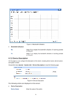
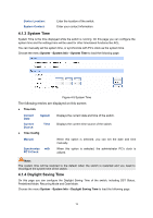
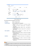
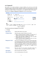
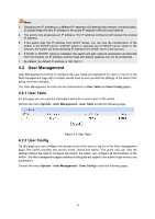
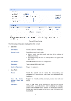
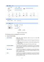
Note: 3. Changing the IP address to a different IP segment will interrupt the network communication, so please keep the new IP address in the same IP segment with the local network. 4. The switch only possesses an IP address. The IP address configured will replace the original IP address. 5. If the switch gets the IP address from DHCP server, you can see the configuration of the switch in the DHCP server; if DHCP option is selected but no DHCP server exists in the network, the switch will keep obtaining IP address from DHCP server until success. 6. If DHCP or BOOTP option is selected, the switch will gets network parameters dynamically from the Internet, so IP address, subnet mask and default gateway can not be configured. 7. By default, the default IP address is 192.168.0.1. 4.2 User Management User Management functions to configure the user name and password for users to log on to the Web management page with a certain access level so as to protect the settings of the switch from being randomly changed. The User Management function can be implemented on User Table and User Config pages. 4.2.1 User Table On this page you can view the information about the current users of the switch. Choose the menu System→User Management→User Table to load the following page. Figure 4-8 User Table 4.2.2 User Config On this page you can configure the access level of the user to log on to the Web management page. The switch provides two access levels: Guest and Admin. The guest only can view the settings without the right to configure the switch; the admin can configure all the functions of the switch. The Web management pages contained in this guide are subject to the admin's login without any explanation. Choose the menu System→User Management→User Config to load the following page. 16
-
 1
1 -
2
-
3
-
4
-
5
-
6
-
7
-
8
-
9
-
10
-
11
-
12
-
13
-
14
-
15
-
16
-
17
-
 18
18 -
 19
19 -
 20
20 -
 21
21 -
 22
22 -
 23
23 -
 24
24 -
 25
25 -
 26
26 -
 27
27 -
 28
28 -
29
-
30
-
31
-
32
-
33
-
34
-
35
-
36
-
37
-
38
-
39
-
40
-
41
-
42
-
43
-
44
-
45
-
46
-
47
-
48
-
49
-
50
-
51
-
52
-
53
-
54
-
55
-
56
-
57
-
58
-
59
-
60
-
61
-
62
-
63
-
64
-
65
-
66
-
67
-
68
-
69
-
70
-
71
-
72
-
73
-
74
-
75
-
76
-
77
-
78
-
79
-
80
-
81
-
82
-
83
-
84
-
85
-
86
-
87
-
88
-
89
-
90
-
91
-
92
-
93
-
94
-
95
-
96
-
97
-
98
-
99
-
100
-
101
-
102
-
103
-
104
-
105
-
106
-
107
-
108
-
109
-
110
-
111
-
112
-
113
-
114
-
115
-
116
-
117
-
118
-
119
-
120
-
121
-
122
-
123
-
124
-
125
-
126
-
127
-
128
-
129
-
130
-
131
-
132
-
133
-
134
-
135
-
136
-
137
-
138
-
139
-
140
-
141
-
142
 |
 |