TP-Link TL-SL2218 TL-SL2218 V1 User Guide - Page 14
Rear Panel, Switching, Port Config, Grounding Terminal, Installation Guide, AC Power Socket
 |
View all TP-Link TL-SL2218 manuals
Add to My Manuals
Save this manual to your list of manuals |
Page 14 highlights
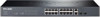
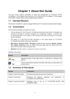
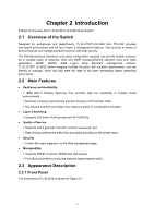
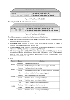
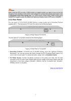
Note: When using the SFP port with a 100M module or a gigabit module, you need to log on to the GUI (Graphical User Interface) of the Switch and configure its corresponding Speed and Duplex mode on Switching→Port→Port Config page. For 100M module, please select 100MFD while select 1000MFD for gigabit module. By default, the Speed and Duplex mode of SFP port is 1000MFD. 2.3.2 Rear Panel The rear panel of TL-SL2218/TL-SL2428 features a power socket and a Grounding Terminal (marked with ). The rear panel of TL-SL2218 is shown as the following figure. Figure 2-3 Rear Panel of TL-SL2218 The rear panel of TL-SL2428 is shown as the following figure. Figure 2-4 Rear Panel of TL-SL2428 ¾ Grounding Terminal: TL-SL2218 and TL-SL2428 already come with Lightning Protection Mechanism. You can also ground the Switch through the PE (Protecting Earth) cable of AC cord or with Ground Cable. For detail information, please refer to Installation Guide. ¾ AC Power Socket: Connect the female connector of the power cord here, and the male connector to the AC power outlet. Please make sure the voltage of the power supply meets the requirement of the input voltage (100-240V~ 50/60Hz 0.3A for TL-SL2218 and 100-240V~ 50/60Hz 0.6A for TL-SL2428 ). Return to CONTENTS 7
-
 1
1 -
2
-
3
-
4
-
5
-
6
-
7
-
8
-
 9
9 -
 10
10 -
 11
11 -
 12
12 -
 13
13 -
 14
14 -
 15
15 -
 16
16 -
 17
17 -
 18
18 -
 19
19 -
20
-
21
-
22
-
23
-
24
-
25
-
26
-
27
-
28
-
29
-
30
-
31
-
32
-
33
-
34
-
35
-
36
-
37
-
38
-
39
-
40
-
41
-
42
-
43
-
44
-
45
-
46
-
47
-
48
-
49
-
50
-
51
-
52
-
53
-
54
-
55
-
56
-
57
-
58
-
59
-
60
-
61
-
62
-
63
-
64
-
65
-
66
-
67
-
68
-
69
-
70
-
71
-
72
-
73
-
74
-
75
-
76
-
77
-
78
-
79
-
80
-
81
-
82
-
83
-
84
-
85
-
86
-
87
-
88
-
89
-
90
-
91
-
92
-
93
-
94
-
95
-
96
-
97
-
98
-
99
-
100
-
101
-
102
-
103
-
104
-
105
-
106
-
107
-
108
-
109
-
110
-
111
-
112
-
113
-
114
-
115
-
116
-
117
-
118
-
119
-
120
-
121
-
122
-
123
-
124
-
125
-
126
-
127
-
128
-
129
-
130
-
131
-
132
-
133
-
134
-
135
-
136
-
137
-
138
-
139
-
140
-
141
-
142
 |
 |