Toshiba Portege M700 PPM70C-03W0GC Users Manual Canada; English - Page 44
Ultra Slim Bay lock
 |
View all Toshiba Portege M700 PPM70C-03W0GC manuals
Add to My Manuals
Save this manual to your list of manuals |
Page 44 highlights
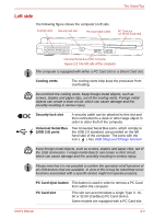
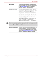
The Grand Tour Memory module slot The slot B memory module is located here. The memory module slot allows for the installation, replacement and removal of additional memory module. Refer to the Additional memory module section in Chapter 3, Hardware, Utilities and Options. HDD pack cover screws The HDD pack cover screws are the screws that hold the hard disk drive cover in place. Hard disk drive This contains a Hard disk drive pack, which can be removed and reinstalled. For more information on how to remove or reinstall, please refer to the HDD Kit (Serial-ATA) section in Chapter 3, Hardware, Utilities and Options. Battery release latch Slide and hold this latch into its 'Unlock' position in order to release the battery pack ready for removal. For more detailed information on removing the battery pack please refer to Chapter 6, Power and Power-Up Modes. Battery lock Slide the battery lock to release the battery pack for removal. Battery pack The battery pack provides power to the computer when the AC adaptor is not connected. For more detailed information on the use and operation of the battery pack please refer to Chapter 6, Power and Power-Up Modes. Ultra Slim Bay Refer to the Right side section in this chapter for details. Ultra Slim Bay latch Slide the latch to release or secure the Ultra Slim Bay latch. Be sure to lock the Ultra Slim Bay latch before you transport or carry the computer. Ultra Slim Bay lock screw (lock position) Lock position is used to lock the Ultra Slim Bay Latch. The Ultra Slim Bay Latch is locked by securing the Ultra Slim Bay Lock screw into the lock position. User's Manual 2-8
-
 1
1 -
2
-
3
-
4
-
5
-
6
-
7
-
8
-
9
-
10
-
11
-
12
-
13
-
14
-
15
-
16
-
17
-
18
-
19
-
20
-
21
-
22
-
23
-
24
-
25
-
26
-
27
-
28
-
29
-
30
-
31
-
32
-
33
-
34
-
35
-
36
-
37
-
38
-
 39
39 -
 40
40 -
 41
41 -
 42
42 -
 43
43 -
 44
44 -
 45
45 -
 46
46 -
 47
47 -
 48
48 -
 49
49 -
50
-
51
-
52
-
53
-
54
-
55
-
56
-
57
-
58
-
59
-
60
-
61
-
62
-
63
-
64
-
65
-
66
-
67
-
68
-
69
-
70
-
71
-
72
-
73
-
74
-
75
-
76
-
77
-
78
-
79
-
80
-
81
-
82
-
83
-
84
-
85
-
86
-
87
-
88
-
89
-
90
-
91
-
92
-
93
-
94
-
95
-
96
-
97
-
98
-
99
-
100
-
101
-
102
-
103
-
104
-
105
-
106
-
107
-
108
-
109
-
110
-
111
-
112
-
113
-
114
-
115
-
116
-
117
-
118
-
119
-
120
-
121
-
122
-
123
-
124
-
125
-
126
-
127
-
128
-
129
-
130
-
131
-
132
-
133
-
134
-
135
-
136
-
137
-
138
-
139
-
140
-
141
-
142
-
143
-
144
-
145
-
146
-
147
-
148
-
149
-
150
-
151
-
152
-
153
-
154
-
155
-
156
-
157
-
158
-
159
-
160
-
161
-
162
-
163
-
164
-
165
-
166
-
167
-
168
-
169
-
170
-
171
-
172
-
173
-
174
-
175
-
176
-
177
-
178
-
179
-
180
-
181
-
182
-
183
-
184
-
185
-
186
-
187
-
188
-
189
-
190
-
191
-
192
-
193
-
194
-
195
-
196
-
197
-
198
-
199
-
200
-
201
-
202
-
203
-
204
-
205
-
206
-
207
-
208
-
209
-
210
-
211
-
212
-
213
-
214
-
215
-
216
-
217
-
218
-
219
-
220
-
221
-
222
-
223
-
224
-
225
-
226
-
227
-
228
-
229
-
230
-
231
-
232
-
233
-
234
-
235
-
236
-
237
-
238
-
239
-
240
-
241
-
242
-
243
-
244
-
245
-
246
-
247
-
248
-
249
-
250
-
251
-
252
-
253
-
254
-
255
-
256
-
257
-
258
-
259
-
260
-
261
-
262
-
263
-
264
-
265
-
266
-
267
-
268
-
269
-
270
-
271
-
272
-
273
-
274
-
275
-
276
-
277
-
278
-
279
-
280
-
281
-
282
 |
 |
