Toshiba Satellite A660-BT3G25X Maintenance Manual
Toshiba Satellite A660-BT3G25X Manual
 |
View all Toshiba Satellite A660-BT3G25X manuals
Add to My Manuals
Save this manual to your list of manuals |
Toshiba Satellite A660-BT3G25X manual content summary:
- Toshiba Satellite A660-BT3G25X | Maintenance Manual - Page 1
Toshiba Personal Computer Satellite & Satellite Pro Maintenance Manual TOSHIBA CORPORATION - Toshiba Satellite A660-BT3G25X | Maintenance Manual - Page 2
Toshiba Personal Computer Satellite Maintenance Manual First edition April.2010 Disclaimer The information presented in this manual has been reviewed and validated for accuracy. The included set of instructions of their respective holders. Satellite A660/ProA660 Series Maintenance Manual ii - Toshiba Satellite A660-BT3G25X | Maintenance Manual - Page 3
cause overheating, smoke or fire. If you replace the battery pack or RTC battery, be sure to use only the same model battery or an equivalent battery recommended by Toshiba. Installation of the wrong battery can cause the battery to explode. Satellite A660/ProA660 Series Maintenance Manual iii - Toshiba Satellite A660-BT3G25X | Maintenance Manual - Page 4
Satellite Series system unit and each FRU. Chapter 2 Troubleshooting Procedures explains how to diagnose and resolve FRU problems. Chapter 3 Test and Diagnostics describes how to perform test and diagnostic operations for maintenance service Satellite A660/ProA660 Series Maintenance Manual iv - Toshiba Satellite A660-BT3G25X | Maintenance Manual - Page 5
. User input Text that you are instructed to type in is shown in the boldface type below: DISKCOPY A: B: The display Text generated by the computer that appears on its display is presented in the typeface below: Format complete System transferred Satellite A660/ProA660 Series Maintenance Manual v - Toshiba Satellite A660-BT3G25X | Maintenance Manual - Page 6
troubleshooting 28 2.11 Bluetooth Troubleshooting 30 2.12 3 in 1 card Troubleshooting 32 2-13 HDD/SSD troubleshooting process 34 2-14 CRT failure troubleshooting process 36 2-15 LAN Troubleshooting ...38 2-16 MIC troubleshooting process 40 Satellite A660/ProA660 Series Maintenance Manual - Toshiba Satellite A660-BT3G25X | Maintenance Manual - Page 7
...18 3.13 LAN Test...20 3.14 RTC Test ...23 3.15 BUTTON Test...24 3.16 1st HDDTest...26 3.17 RDMI Test ...27 3.18 WDMI Test ...28 Satellite A660/ProA660 Series Maintenance Manual vii - Toshiba Satellite A660-BT3G25X | Maintenance Manual - Page 8
Shanks 4-8 Symbols of Screws on the Laptop Body 4-8 Symbol examples ...4-8 4.2 Battery...4-9 Removing the Battery Pack 4-9 Installing the Battery Pack 4-10 4.3 HDD...4-11 Removing the ODD Bay Module 4-23 Installing the ODD Bay Module 4-24 Satellite A660/ProA660 Series Maintenance Manual viii - Toshiba Satellite A660-BT3G25X | Maintenance Manual - Page 9
the Indicator Board 4-39 4.15 USB Board ...4-40 Removing the USB Board 4-40 Installing the USB Board 4-40 4.16 Bluetooth...4-41 Removing the Bluetooth 4-41 Satellite A660/ProA660 Series Maintenance Manual ix - Toshiba Satellite A660-BT3G25X | Maintenance Manual - Page 10
Panel 4-60 4.25 Web Camera ...4-61 Removing the Web Camera 4-61 Installing the Web Camera 4-61 4.26 WLAN Antennas ...4-62 Removing the WLAN Antennas 4-62 Satellite A660/ProA660 Series Maintenance Manual x - Toshiba Satellite A660-BT3G25X | Maintenance Manual - Page 11
4.1 Removing the Battery Pack 4-9 Figure laptop 4-26 Figure 4.19 Disconnecting the cables and removing the upper logic assembly screw ........ 4-27 Figure 4.20 Removing the logic upper assembly 4-27 Figure 4.21 Disassembling the Slot-load ODD 4-30 Satellite A660/ProA660 Series Maintenance Manual - Toshiba Satellite A660-BT3G25X | Maintenance Manual - Page 12
display assembly 4-61 Figure 4.50 Removing the WLAN antennas from the display assembly 4-62 Figure 4.51 Routing the WLAN antennas onto the display assembly 4-63 Satellite A660/ProA660 Series Maintenance Manual xii - Toshiba Satellite A660-BT3G25X | Maintenance Manual - Page 13
A Handling the LCD Module A-1 Appendix B Board Layout...B-1 Appendix C Pin Assignments...C-1 Appendix D Keyboard Scan/Character Codes D-1 Appendix E Key Layout ...E-1 Appendix F Series Screw Torque List F-1 Appendix G Reliability...G-1 Satellite A660/ProA660 Series Maintenance Manual xiii - Toshiba Satellite A660-BT3G25X | Maintenance Manual - Page 14
1 Hardware Overview Chapter 1 Hardware Overview Satellite A660/Pro A660 Maintenance Manual 1-i - Toshiba Satellite A660-BT3G25X | Maintenance Manual - Page 15
1.2 2.5-inch HDD ...1-11 1.3 DVD Super Multi (+-R Double Layer 1-12 1.4 BD-RE and BD-Combo drives 1-13 1.5 Power Supply ...1-14 1.6 Batteries...1-16 1.6.1 Main Battery 1-16 1.6.2 Battery Charging Control 1-16 1.6.3 RTC Battery 1-17 Satellite A660/Pro A660 Maintenance Manual 1-ii - Toshiba Satellite A660-BT3G25X | Maintenance Manual - Page 16
1-12 BD-RE or BD-Combo drive (depending on the model 1-13 Tables Table 1-1 Table 1-2 Table 1-3 Table 1-4 HDD Specifications 1-11 DVD Super Multi Drive Specifications 1-12 Blu-ray Disc Drive specifications 1-13 Quick/Normal Charging Time 1-16 Satellite A660/Pro A660 Maintenance Manual 1-iii - Toshiba Satellite A660-BT3G25X | Maintenance Manual - Page 17
- Toshiba Satellite A660-BT3G25X | Maintenance Manual - Page 18
/500/640GB SATA (5,400rpm) 320/500GB SATA (7,200rpm) 64GB/128/256/512GB TOSHIBA solid-state drive (SSD) ODD (BTO) 12.7mm height DVD Super Multi drive (supporting DVD-R / -RW / +R / +RW / -RAM / -RDL / +RDL / CD-R / CD-RW) Double Layer with Labelflash Satellite A660/Pro A660 Maintenance Manual 1-1 - Toshiba Satellite A660-BT3G25X | Maintenance Manual - Page 19
DDR3, 512/1024MB) Keyboard (BTO) The computer is equipped with an illuminated Toshiba 2010 A4 keyboard with 102 keys, including number pad. It is a Win7 port provides support for VESA DDC2B compatible functions. A WDDM driver is ready for Windows 7. Satellite A660/Pro A660 Maintenance Manual 1-2 - Toshiba Satellite A660-BT3G25X | Maintenance Manual - Page 20
The external eSATA/USB combo port executes high-speed data transfers to external devices and now supports shielded cable lengths of up to 2 meters outside the computer. The port also complies with and receive SD and HD video/audio and control signals. Satellite A660/Pro A660 Maintenance Manual 1-3 - Toshiba Satellite A660-BT3G25X | Maintenance Manual - Page 21
connection of a stereo device for audio input. LAN (BTO) The computer has built-in support for Gigabit Ethernet LAN (1000 megabits per second, 1000BASE-T) and 10M/100M Ethernet LAN (10 , providing easy maintenance and long-term reliability. Satellite A660/Pro A660 Maintenance Manual 1-4 - Toshiba Satellite A660-BT3G25X | Maintenance Manual - Page 22
The integrated sound system provides support for the computer's internal speakers and microphone, also allowing an external microphone and headphones to be connected via the appropriate jacks. The computer has two Harman or Kardon (Odyssey2) speakers. Satellite A660/Pro A660 Maintenance Manual 1-5 - Toshiba Satellite A660-BT3G25X | Maintenance Manual - Page 23
1 Hardware Overview Figure 1-1A shows the computer and its system unit configuration. Figure 1-1A ID Parts Description Placement Part A Satellite A660/Pro A660 Maintenance Manual 1-6 - Toshiba Satellite A660-BT3G25X | Maintenance Manual - Page 24
1 Hardware Overview Satellite A660/Pro A660 Maintenance Manual 1-7 - Toshiba Satellite A660-BT3G25X | Maintenance Manual - Page 25
1 Hardware Overview Satellite A660/Pro A660 Maintenance Manual 1-8 - Toshiba Satellite A660-BT3G25X | Maintenance Manual - Page 26
volume output control External LED control Battery scope report and control Sticky key support Power switch control Two host interface channels support Supports three independent devices Internal Keyboard country selection Wireless LAN on/off button Satellite A660/Pro A660 Maintenance Manual 1-9 - Toshiba Satellite A660-BT3G25X | Maintenance Manual - Page 27
support Software EQ support Synchronize to change video and audio output to HDMI/DP MAXX audio support by SW solution (BTO by image) Wireless LAN Controller Realtek 802.11b/g, 8191SE (1x2) Atheros 802.11 HB95 (1x1) PumaPeak 802.11a/b/g (2x2), a/b/g/n (2x2) Satellite A660/Pro A660 Maintenance Manual - Toshiba Satellite A660-BT3G25X | Maintenance Manual - Page 28
5400 RPM 9.5 mm 312,581,808 512 Specifications 250G 5400 or 7200 RPM 9.5 mm 488,397,168 512 320 GB 5400 or 7200 RPM 9.5 mm 625,142,448 512 500GB 5400 or 7200 RPM 9.5 mm 976,773,168 512 Specifications 640 GB 5400 RPM 9.5 mm 1,250,263,728 512 Satellite A660/Pro A660 Maintenance Manual 1-11 - Toshiba Satellite A660-BT3G25X | Maintenance Manual - Page 29
130 Data Buffer Size (Mbytes) 2MB DVD: Formats Supported DVD-VIDEO, DVD-ROM, DVD-R, DVD-RW, DVD-RAM, DVD+R, DVD+-R (Double Layer), DVD+RW. CD: CD-DA, CD-ROM, CD-R, CD-RW, CD-ROMXA, Photo CD (Multi-Session), Video CD, CD-Extra (CD+), CD-Text. Satellite A660/Pro A660 Maintenance Manual 1-12 - Toshiba Satellite A660-BT3G25X | Maintenance Manual - Page 30
Blu-ray Disc Drive specifications Item BD-ROM Mode Supported DVD: DVD-VIDEO, DVD-ROM, DVD-R, DVD-RW, DVD-RAM, DVD+R, DVD+-R (Double Layer), DVD+RW. CD: CD-DA, CD-ROM, CD-R, CD-RW, CD-ROMXA, Photo CD (Multi-Session), Video CD, CD-Extra (CD+), CD-Text. Satellite A660/Pro A660 Maintenance Manual - Toshiba Satellite A660-BT3G25X | Maintenance Manual - Page 31
display Turns on the Power LED (in White). Battery indicator (in White or Amber). DC-IN indicator (in White color) 5. External interface Performs communication through the I2C bus (via the internal EC/KBC). Transfers the power supply operation mode. Satellite A660/Pro A660 Maintenance Manual 1-14 - Toshiba Satellite A660-BT3G25X | Maintenance Manual - Page 32
the voltage output to the system block (load/logic circuit side). Monitors the voltage, over-voltage, input/output current of the battery pack. Monitors the internal temperature of the battery pack. Monitors the supply voltage from the AC adapter. Satellite A660/Pro A660 Maintenance Manual 1-15 - Toshiba Satellite A660-BT3G25X | Maintenance Manual - Page 33
, the battery is charged by off-state charge when the system is powered off or by on-state charge when it is powered on. Table 1-4 Quick/Normal Charging Time State Off-State Charge On-State Charge 3, 6 or 12 Cell 3, 6 or 12 Cell Charge Time 4 hours max 12 hours max Satellite A660/Pro A660 - Toshiba Satellite A660-BT3G25X | Maintenance Manual - Page 34
circuit drops below the predetermined value. 2. The charging time exceeds the fixed limit. 1.6.3 RTC Battery The RTC battery provides power to maintain the current date, time and other system information in memory while the computer is turned off. Satellite A660/Pro A660 Maintenance Manual 1-17 - Toshiba Satellite A660-BT3G25X | Maintenance Manual - Page 35
Media slot Troubleshooting 42 2.17 HDD/SSD Troubleshooting 44 2.18 CRT failure Troubleshooting 46 2.19 HDMI CEC Troubleshooting 48 2.20 MIC Troubleshooting 50 2.21 Finger print Troubleshooting 52 2.22 E-SATA Troubleshooting 54 2.23 Felica Troubleshooting 56 2.24 JET Troubleshooting 58 2.25 - Toshiba Satellite A660-BT3G25X | Maintenance Manual - Page 36
2-27 Sleep and Play music troubleshooting process 66 Figure 2-28 Wimax Troubleshooting process 68 Figure 2-29 3G troubleshooting process 70 Figure 2-30 LAN troubleshooting process 73 Figure 2-31 Ambient Light Sensor troubleshooting process 75 SatelliteA660/ProA660 Series Maintenance Manual 2 - Toshiba Satellite A660-BT3G25X | Maintenance Manual - Page 37
2 Troubleshooting Procedures Tables Table 2-1 Table 2-2 Battery LED ...121 DC-IN LED...142 SatelliteA660/ProA660 Series Maintenance Manual 3 - Toshiba Satellite A660-BT3G25X | Maintenance Manual - Page 38
procedures are given in Chapter 4. The following tools are necessary for implementing the troubleshooting procedures: 1. Phillips screwdriver (3.5 mm) 2. 2DD or 2HD formatted work disk HDD 16. Felica card 17. Remote controller 18. HDMI 19. CRT SatelliteA660/ProA660 Series Maintenance Manual 4 - Toshiba Satellite A660-BT3G25X | Maintenance Manual - Page 39
, turn directly to the appropriate section of this chapter. If the problem is unspecified, use the flowchart in Figure 2-1 as a guide for determining which troubleshooting procedures to execute. Before performing any troubleshooting procedures, verify the following: Ask the user if a password is - Toshiba Satellite A660-BT3G25X | Maintenance Manual - Page 40
indow s7 being loaded? Yes A Perform the Pow er Supply No Troubleshooting procedures in section 2.3 Perform the Pow er Supply No T roubleshooting procedures .EX E and select the H A R D D ISK item . Figure 2-1 Troubleshooting flowchart (1/2) SatelliteA660/ProA660 Series Maintenance Manual 6 - Toshiba Satellite A660-BT3G25X | Maintenance Manual - Page 41
USB memory No disk or CD ROM Troubleshooting procedures in section 2.5 After confirming which diagnostics test has detected Yes an error, perform the appropriate procedure as outlined below. End Figure 2-1 Troubleshooting flowchart (2/2) SatelliteA660/ProA660 Series Maintenance Manual 7 - Toshiba Satellite A660-BT3G25X | Maintenance Manual - Page 42
should be executed several times to isolate the problem. When a problem has been located, perform the appropriate troubleshooting procedures as follows: 1. If an error is detected by the battery test, perform the Power Supply Troubleshooting procedures in Section 2.3 2. If an error is detected - Toshiba Satellite A660-BT3G25X | Maintenance Manual - Page 43
Section 2.23 15. If an error is detected when using the JET, perform the JET troubleshooting procedures in Section 2.24 16. If an error is detected when using the Sleep charge, perform the Sleep & Charge troubleshooting procedures in Section 2.26 SatelliteA660/ProA660 Series Maintenance Manual 9 - Toshiba Satellite A660-BT3G25X | Maintenance Manual - Page 44
29 20. If an error is detected when using the 3G, perform the 3G troubleshooting procedures in Section 2.30 21. If an error is detected when using the Ambient Light Sensor, perform the Ambient Light Sensor troubleshooting procedures in Section 2.32 SatelliteA660/ProA660 Series Maintenance Manual 10 - Toshiba Satellite A660-BT3G25X | Maintenance Manual - Page 45
Replace adaptor / battery (Procedure 2) Can you turn the computer on? No Are the internal power connections secure? Y es Replace system board Yes Run diagnostic program (Procedure 4) Perform internal connection No check (Procedure 5) END SatelliteA660/ProA660 Series Maintenance Manual 11 - Toshiba Satellite A660-BT3G25X | Maintenance Manual - Page 46
(LED on for 1 second remaining every 4 seconds) Amber, blinking Battery within critical low state: 3 (LED every on for 1 second 2 seconds) minutes remaining. The system is protected and cannot be re-powered without the AC power connected. on SatelliteA660/ProA660 Series Maintenance Manual 12 - Toshiba Satellite A660-BT3G25X | Maintenance Manual - Page 47
2 Troubleshooting Procedures Amber color off Battery not in low or critical low state; It's in discharging state SatelliteA660/ProA660 Series Maintenance Manual 13 - Toshiba Satellite A660-BT3G25X | Maintenance Manual - Page 48
adaptor may not supply power or may not charge the battery. Perform Check 1. Check 1 Connect a new AC adaptor. If the problem is not resolved, go to Check 2. Check 2 Insert a new battery. If the problem is still not resolved, go to Procedure 3. SatelliteA660/ProA660 Series Maintenance Manual 14 - Toshiba Satellite A660-BT3G25X | Maintenance Manual - Page 49
, go to Procedure 4. • If the battery LED does not light, go to Check 6. Check 6 Make sure the battery pack is installed in the computer correctly. If the battery is properly installed and the battery LED still does not light, go to Procedure 4. SatelliteA660/ProA660 Series Maintenance Manual 15 - Toshiba Satellite A660-BT3G25X | Maintenance Manual - Page 50
no problem is detected, the battery is battery cable is firmly connected to the system board. If it is connected firmly, go to Check 3. Check 3 The system board may be damaged. Replace it with a new one following the instructions in Chapter 4. SatelliteA660/ProA660 Series Maintenance Manual - Toshiba Satellite A660-BT3G25X | Maintenance Manual - Page 51
a display problem detected? D isplay is not No faulty. C ontinue tro u b le s h o o tin g - refer to Figure 2-1 Yes Perform connector and replacem ent check (Procedure 3) R eplace system board END Figure 2-3 Display troubleshooting process SatelliteA660/ProA660 Series Maintenance Manual 17 - Toshiba Satellite A660-BT3G25X | Maintenance Manual - Page 52
Troubleshooting Procedures This section describes how to determine if the computer's display is functioning properly. The process is outlined in Figure 2-3. Start with Procedure 1 and continue with the other procedures as instructed same problem as SatelliteA660/ProA660 Series Maintenance Manual 18 - Toshiba Satellite A660-BT3G25X | Maintenance Manual - Page 53
and test display again. If the problem still exists, perform Check 4. Check 4 Replace the CPU with another of the same specifications. If the problem still exists, perform Check 5. Check 5 The system board may be damaged. Replace it with a new one. SatelliteA660/ProA660 Series Maintenance Manual 19 - Toshiba Satellite A660-BT3G25X | Maintenance Manual - Page 54
Procedures 2.5 Keyboard Troubleshooting STA RT P e rfo rm d ia g n o stic c h e ck (P ro ced u re 1 ) W as a k eyb re p la c e m e n t c h e c k (P ro ced u re 2 ) R e p la c e sy ste m b o a rd EN D Figure 2-4 Keyboard troubleshooting process SatelliteA660/ProA660 Series Maintenance Manual 20 - Toshiba Satellite A660-BT3G25X | Maintenance Manual - Page 55
The keyboard may be damaged. Replace it with a new one following the instructions in Chapter 4. If the problem still exists, perform Check 3. Check 3 The system board may be damaged. Replace it with a new one following the instructions in Chapter 4. SatelliteA660/ProA660 Series Maintenance Manual 21 - Toshiba Satellite A660-BT3G25X | Maintenance Manual - Page 56
Procedures 2.6 External USB Devices Troubleshooting STA RT P erfo rm ex tern al d ev ice an d c o n n ec tio n c h ec k (P rocedure 1) u lty No R ep lace sy stem b o ard (P rocedure 2) END Figure 2-5 External USB device troubleshooting process SatelliteA660/ProA660 Series Maintenance Manual 22 - Toshiba Satellite A660-BT3G25X | Maintenance Manual - Page 57
same problem as the original device, the system board or USB small board may be damaged. Go to Procedure 2. Procedure 2 Replace system board If the error persists, the system board or USB small board may be damaged. Replace it with a new one following the instructions in Chapter 4. SatelliteA660 - Toshiba Satellite A660-BT3G25X | Maintenance Manual - Page 58
Procedures 2.7 TV-Tuner Failure Troubleshooting START IS D B -T DVBT & DMBT Perform T V T uner C able connection check (Procedure 1) Perform TV Tuner B -C A ro p e rly ? No R eplace system board END Figure 2-6 TV-out troubleshooting process SatelliteA660/ProA660 Series Maintenance Manual 24 - Toshiba Satellite A660-BT3G25X | Maintenance Manual - Page 59
Troubleshooting Procedures To determine if the computer's TV Tuner port is functioning properly, perform the following procedures. Figure 2-6 outlines the process. Start with Procedure 1 and continue as instructed the instructions in Chapter 4. SatelliteA660/ProA660 Series Maintenance Manual 25 - Toshiba Satellite A660-BT3G25X | Maintenance Manual - Page 60
Procedures 2.8 Touch Pad Troubleshooting STA RT P erfo rm T o u ch p ad check (P ro ced u re 1 ) D oes T a n d re p la c e m e n t c h e c k (P ro ced u re 3 ) R e p la c e sy ste m b o a rd END Figure 2-7 Touchpad troubleshooting process SatelliteA660/ProA660 Series Maintenance Manual 26 - Toshiba Satellite A660-BT3G25X | Maintenance Manual - Page 61
Troubleshooting Procedures To determine if the computer's built-in Touchpad is functioning properly, perform the following procedures. Figure 2-7 outlines the process. Start with Procedure 1 and continue as instructed the steps in Chapter 4. SatelliteA660/ProA660 Series Maintenance Manual 27 - Toshiba Satellite A660-BT3G25X | Maintenance Manual - Page 62
Procedures 2.9 Speaker Troubleshooting START P erform aud io source test (P rocedure 1) D o all so urces have No (P rocedure 3) P erform replacem ent check (P rocedure 4) R eplace system b oard END Figure 2-8 Speaker troubleshooting process SatelliteA660/ProA660 Series Maintenance Manual 28 - Toshiba Satellite A660-BT3G25X | Maintenance Manual - Page 63
2 Troubleshooting Procedures To determine if the computer's built-in speakers are functioning properly, perform the following procedures. Figure 2-8 outlines the process. First adjust the speaker volume to an appropriate level. Start with Procedure 1 and continue as instructed. Procedure 1: Audio - Toshiba Satellite A660-BT3G25X | Maintenance Manual - Page 64
Procedures 2.10 Optical Drive Troubleshooting START Perform audio CD check (Procedure 1) Audio CD functions ok? Perform drive- No diagnostic test (Procedure 4) Perform connection and replacement check (Procedure 5) Replace system board END SatelliteA660/ProA660 Series Maintenance Manual 30 - Toshiba Satellite A660-BT3G25X | Maintenance Manual - Page 65
Procedures Figure 2-9 Optical drive troubleshooting process This section describes how to determine if the computer's internal optical drive is functioning properly. The Satellite/Satellite Pro A660/A665/A667 Series/Dynabook TX/AX Series Maintenance Manual module bays can accommodate the - Toshiba Satellite A660-BT3G25X | Maintenance Manual - Page 66
2 Troubleshooting Procedures Procedure 4 Connection check and replacement check The optical drive connects to the 3. Check 3 The system board may be damaged. Replace it with new one following the instructions in Chapter 4, Replacement Procedures. SatelliteA660/ProA660 Series Maintenance Manual 32 - Toshiba Satellite A660-BT3G25X | Maintenance Manual - Page 67
Troubleshooting START Perform telephone line connection check (Procedure 1) Computer unable to detect telephone signal? Check / replace Yes telephone line and connections No Perform connection check (Procedure 2) Perform replacement check (Procedure 3) Replace system board END SatelliteA660 - Toshiba Satellite A660-BT3G25X | Maintenance Manual - Page 68
2Troubleshooting Procedures Figure 2-10 Modem troubleshooting process SatelliteA660/ProA660 Series Maintenance Manual 34 - Toshiba Satellite A660-BT3G25X | Maintenance Manual - Page 69
connected to the system board. If the problem persists, perform Procedure 3. Procedure 3 problem persists, the system board may be defective or damaged. Replace the System Board with a new one following the steps in Chapter 4, Replacement Procedures. SatelliteA660/ProA660 Series Maintenance Manual - Toshiba Satellite A660-BT3G25X | Maintenance Manual - Page 70
card Troubleshooting START Perform Express card test (Procedure 1) D o errors occur during Express card test? Express card unit No is not faulty. Yes Perform Express card socket replacem ent check (Procedure 2) R eplace system board END SatelliteA660/ProA660 Series Maintenance Manual 36 - Toshiba Satellite A660-BT3G25X | Maintenance Manual - Page 71
2Troubleshooting Procedures Figure 2-11 Express card troubleshooting process SatelliteA660/ProA660 Series Maintenance Manual 37 - Toshiba Satellite A660-BT3G25X | Maintenance Manual - Page 72
the computer following the steps described in Chapter 4, Replacement Procedures and replace the socket. If the problem persists, the system board may be defective or damaged. Replace the system board with a new one following the steps in Chapter 4. SatelliteA660/ProA660 Series Maintenance Manual 38 - Toshiba Satellite A660-BT3G25X | Maintenance Manual - Page 73
Was a wireless LAN problem delected? Yes Perform connector and replacement check (Procedure 2) Wireless LAN system No is not faulty. Continue troubleshooting - refer to Figure 2-10 Replace wireless LAN antenna/unit Replace system board END SatelliteA660/ProA660 Series Maintenance Manual 39 - Toshiba Satellite A660-BT3G25X | Maintenance Manual - Page 74
2Troubleshooting Procedures Figure 2-12 Wireless LAN troubleshooting process Notes: W/L Antenna assemble rule as below: damaged. Replace it with a new one following the instructions in Chapter 4. If the problem still exists, perform Check 4. SatelliteA660/ProA660 Series Maintenance Manual 40 - Toshiba Satellite A660-BT3G25X | Maintenance Manual - Page 75
2Troubleshooting Procedures Check 4 The system board may be damaged. Replace it with a new one following the instructions in Chapter 4. SatelliteA660/ProA660 Series Maintenance Manual 41 - Toshiba Satellite A660-BT3G25X | Maintenance Manual - Page 76
2Troubleshooting Procedures 2.14 Camera Troubleshooting SatelliteA660/ProA660 Series Maintenance Manual 42 - Toshiba Satellite A660-BT3G25X | Maintenance Manual - Page 77
Procedures Figure 2-13 Camera troubleshooting process The Camera board instructions in Chapter 4. If the problem still exists, perform Check 3. Check 3 The system board may be damaged. Replace it with a new one following the instructions in Chapter 4. SatelliteA660/ProA660 Series Maintenance Manual - Toshiba Satellite A660-BT3G25X | Maintenance Manual - Page 78
2Troubleshooting Procedures 2.15 Bluetooth Troubleshooting SatelliteA660/ProA660 Series Maintenance Manual 44 - Toshiba Satellite A660-BT3G25X | Maintenance Manual - Page 79
Figure 2-14 Bluetooth troubleshooting process The Bluetooth antenna instructions in Chapter 4. If the problem still exists, perform Check 4. Check 4 The system board may be damaged. Replace it with a new one following the instructions in Chapter 4. SatelliteA660/ProA660 Series Maintenance Manual - Toshiba Satellite A660-BT3G25X | Maintenance Manual - Page 80
2Troubleshooting Procedures SatelliteA660/ProA660 Series Maintenance Manual 46 - Toshiba Satellite A660-BT3G25X | Maintenance Manual - Page 81
2Troubleshooting Procedures 2.16 Bridge Media Slot Troubleshooting START Perform Bridge Media Slot test (Procedure 1) Do errors occur during replacement check (Procedure 2) Replace system board END Figure 2-15 5 in 1 card troubleshooting process SatelliteA660/ProA660 Series Maintenance Manual 47 - Toshiba Satellite A660-BT3G25X | Maintenance Manual - Page 82
the computer following the steps described in Chapter 4, Replacement Procedures and replace the socket. If the problem persists, the system board may be defective or damaged. Replace the system board with a new one following the steps in Chapter 4. SatelliteA660/ProA660 Series Maintenance Manual 48 - Toshiba Satellite A660-BT3G25X | Maintenance Manual - Page 83
2Troubleshooting Procedures SatelliteA660/ProA660 Series Maintenance Manual 49 - Toshiba Satellite A660-BT3G25X | Maintenance Manual - Page 84
2Troubleshooting Procedures 2.17 HDD/SSD Troubleshooting Figure 2-16 HDD/SDD troubleshooting process SatelliteA660/ProA660 Series Maintenance Manual 50 - Toshiba Satellite A660-BT3G25X | Maintenance Manual - Page 85
HDD module may be damaged. Replace it with a new one following the instructions in Chapter 4. If the problem still exists, perform Check 3. Check 3 The system board may be damaged. Replace it with a new one following the instructions in Chapter 4. SatelliteA660/ProA660 Series Maintenance Manual 51 - Toshiba Satellite A660-BT3G25X | Maintenance Manual - Page 86
2Troubleshooting Procedures 2.18 CRT Troubleshooting STA RT P e rfo rm C R T c o n n e c tio n check (P ro ced u re 1 ) D o e s re p la c e m e n t re n t C R T set C heck C R T P o rt c o n n e c tio n Figure 2-17 CRT troubleshooting process SatelliteA660/ProA660 Series Maintenance Manual 52 - Toshiba Satellite A660-BT3G25X | Maintenance Manual - Page 87
procedures. Figure 2-17 outlines the process. Start with Procedure 1 and continue as instructed. Procedure 1: CRT connection check Procedure 2: CRT set check Procedure 1 CRT Replace it with a new one following the instructions in Chapter 4. SatelliteA660/ProA660 Series Maintenance Manual 53 - Toshiba Satellite A660-BT3G25X | Maintenance Manual - Page 88
2Troubleshooting Procedures 2.19 HDMI CEC Troubleshooting STA R T P erfo rm H D M I co n n ectio n check (P rocedure 1) D oes replacem ent H D M I c a b sy stem b o ard No U se differen t H D M I set END Figure 2-18 HDMI troubleshooting process SatelliteA660/ProA660 Series Maintenance Manual 54 - Toshiba Satellite A660-BT3G25X | Maintenance Manual - Page 89
procedures. Figure 2-18 outlines the process. Start with Procedure 1 and continue as instructed. Procedure 1: HDMI connection check Procedure 2: HDMI set check Procedure 1 HDMI . Replace it with a new one following the instructions in Chapter 4. SatelliteA660/ProA660 Series Maintenance Manual 55 - Toshiba Satellite A660-BT3G25X | Maintenance Manual - Page 90
2Troubleshooting Procedures 2.20 MIC Troubleshooting Figure 2-19. MIC troubleshooting process SatelliteA660/ProA660 Series Maintenance Manual 56 - Toshiba Satellite A660-BT3G25X | Maintenance Manual - Page 91
The MIC line may be damaged. Replace it with a new one following the instructions in Chapter 4. If the problem still exists, perform Check 3. Check 3 The system board may be damaged. Replace it with a new one following the instructions in Chapter 4. SatelliteA660/ProA660 Series Maintenance Manual 57 - Toshiba Satellite A660-BT3G25X | Maintenance Manual - Page 92
2Troubleshooting Procedures 2.21 Finger printer troubleshooting Figure 2-20 Finger printer troubleshooting process SatelliteA660/ProA660 Series Maintenance Manual 58 - Toshiba Satellite A660-BT3G25X | Maintenance Manual - Page 93
board may be damaged. Replace it with a new one following the instructions in Chapter 4. If the problem still exists, perform Check 3. Check 3 The system board may be damaged. Replace it with a new one following the instructions in Chapter 4. SatelliteA660/ProA660 Series Maintenance Manual 59 - Toshiba Satellite A660-BT3G25X | Maintenance Manual - Page 94
check (Procedure 2) E-SATA port and No Was an E-SATA problem detected? transmission are not No faulty. Continue troubleshooting - refer to Figure 2.1 Yes Perform connection and replacement check (Procedure 3) Replace system board END SatelliteA660/ProA660 Series Maintenance Manual 60 - Toshiba Satellite A660-BT3G25X | Maintenance Manual - Page 95
to the computer. If the device is able to communicate with the computer, the problem may be intermittent or connections may be faulty. Go to Procedure 2. If communication is . Replace it with a new one following the instructions in Chapter 4. SatelliteA660/ProA660 Series Maintenance Manual 61 - Toshiba Satellite A660-BT3G25X | Maintenance Manual - Page 96
2Troubleshooting Procedures SatelliteA660/ProA660 Series Maintenance Manual 62 - Toshiba Satellite A660-BT3G25X | Maintenance Manual - Page 97
2Troubleshooting Procedures 2.23 Felica Troubleshooting Figure 2-22 Felica troubleshooting process SatelliteA660/ProA660 Series Maintenance Manual 63 - Toshiba Satellite A660-BT3G25X | Maintenance Manual - Page 98
connected to the Felica and system board. Refer to Chapter 4, Replacement Procedures, for instructions on how to disassemble the computer and then perform the following checks. Use windows application a new one following the steps in Chapter 4. SatelliteA660/ProA660 Series Maintenance Manual 64 - Toshiba Satellite A660-BT3G25X | Maintenance Manual - Page 99
2Troubleshooting Procedures 2.24 JET Troubleshooting Figure 2-23 JET troubleshooting process SatelliteA660/ProA660 Series Maintenance Manual 65 - Toshiba Satellite A660-BT3G25X | Maintenance Manual - Page 100
JET module may be damaged. Replace it with a new one following the instructions in Chapter 4. If the problem still exists, perform Check 4. Check 4 The system board may be damaged. Replace it with a new one following the instructions in Chapter 4. SatelliteA660/ProA660 Series Maintenance Manual 66 - Toshiba Satellite A660-BT3G25X | Maintenance Manual - Page 101
2Troubleshooting Procedures SatelliteA660/ProA660 Series Maintenance Manual 67 - Toshiba Satellite A660-BT3G25X | Maintenance Manual - Page 102
2Troubleshooting Procedures 2.25 3D Sensor Troubleshooting SatelliteA660/ProA660 Series Maintenance Manual 68 - Toshiba Satellite A660-BT3G25X | Maintenance Manual - Page 103
2Troubleshooting Procedures Figure 2-24 3D sensor troubleshooting process The operation or system board may be the reason of 3D sensor fault Check 2 The system board may be damaged. Replace it with a new one following the instructions in Chapter 4. SatelliteA660/ProA660 Series Maintenance Manual 69 - Toshiba Satellite A660-BT3G25X | Maintenance Manual - Page 104
2Troubleshooting Procedures SatelliteA660/ProA660 Series Maintenance Manual 70 - Toshiba Satellite A660-BT3G25X | Maintenance Manual - Page 105
2Troubleshooting Procedures 2.26 Sleep & Charge Troubleshooting Figure 2-25 Sleep & Charge troubleshooting process SatelliteA660/ProA660 Series Maintenance Manual 71 - Toshiba Satellite A660-BT3G25X | Maintenance Manual - Page 106
. Start with Procedure 1 and continue with the other procedures as instructed. Procedure 1: windows application test Procedure 2: Replacement check Procedure 1 windows may be damaged. Replace it with a new one following the instructions in Chapter 4. SatelliteA660/ProA660 Series Maintenance Manual 72 - Toshiba Satellite A660-BT3G25X | Maintenance Manual - Page 107
2Troubleshooting Procedures SatelliteA660/ProA660 Series Maintenance Manual 73 - Toshiba Satellite A660-BT3G25X | Maintenance Manual - Page 108
2Troubleshooting Procedures 2.27 CIR Troubleshooting Figure 2-26 CIR troubleshooting process SatelliteA660/ProA660 Series Maintenance Manual 74 - Toshiba Satellite A660-BT3G25X | Maintenance Manual - Page 109
process. Start with Procedure 1 and continue with the other procedures as instructed. Procedure 1: Windows Application test Procedure 2: Connector and replacement check be damaged. Replace it with a new one following the instructions in Chapter 4. SatelliteA660/ProA660 Series Maintenance Manual 75 - Toshiba Satellite A660-BT3G25X | Maintenance Manual - Page 110
2Troubleshooting Procedures 2.28 Sleep & Play music Troubleshooting Figure 2-27 Sleep & Play music troubleshooting process SatelliteA660/ProA660 Series Maintenance Manual 76 - Toshiba Satellite A660-BT3G25X | Maintenance Manual - Page 111
. Start with Procedure 1 and continue with the other procedures as instructed. Procedure 1: windows application test Procedure 2: Replacement check Procedure 1 windows be damaged. Replace it with a new one following the instructions in Chapter 4. SatelliteA660/ProA660 Series Maintenance Manual 77 - Toshiba Satellite A660-BT3G25X | Maintenance Manual - Page 112
check (Procedure 1) Was a Wimax problem delected? Yes Perform connector and replacement check (Procedure 2) Wimax system is not No faulty. Continue troubleshooting - refer to Figure 2-1 Replace Wimax antenna/unit Replace system board END SatelliteA660/ProA660 Series Maintenance Manual 78 - Toshiba Satellite A660-BT3G25X | Maintenance Manual - Page 113
Procedures Figure 2-28 Wimax troubleshooting process Notes: Wimax Antenna instructions in Chapter 4. If the problem still exists, perform Check 4. The system board may be damaged. Replace it with a new one following the instructions in Chapter 4. SatelliteA660/ProA660 Series Maintenance Manual - Toshiba Satellite A660-BT3G25X | Maintenance Manual - Page 114
(Procedure 1) W as a 3G problem detected? Y es Perform system info and electric w ave check (Procedure 2) 3G system is not No faulty. C ontinue troubleshooting - refer to F igure 2.1 R To determine if the computer's wireless LAN system is SatelliteA660/ProA660 Series Maintenance Manual 80 - Toshiba Satellite A660-BT3G25X | Maintenance Manual - Page 115
Application check 1.> Please use TOSHIBA wireless manager. It displays the name of Telecommunication Company, and intensity of an electric wave. 2.> Please choose "About" and click "System Info". "System Info" the Following data is displayed. SatelliteA660/ProA660 Series Maintenance Manual 81 - Toshiba Satellite A660-BT3G25X | Maintenance Manual - Page 116
module. Replace it with a new one following the instructions in Chapter 4. If the problem still exists, perform Check 5. Check 5 If information of SIM card is not displayed, please replace it with a new one following the instructions in Chapter 4. SatelliteA660/ProA660 Series Maintenance Manual 82 - Toshiba Satellite A660-BT3G25X | Maintenance Manual - Page 117
2Troubleshooting Procedures 2.31 LAN Troubleshooting STA RT P e rfo rm d ia g n o stic check (P ro ced u re 2 ) W as a L A N p ro b le m d e re fe r to F ig u re 2 -1 R e p la c e sy ste m b o a rd EN D Figure 2-30 LAN troubleshooting process SatelliteA660/ProA660 Series Maintenance Manual 83 - Toshiba Satellite A660-BT3G25X | Maintenance Manual - Page 118
2. Check 2 The LAN cable may be damaged. Replace it with a new one and repeat Procedure 2. If the problem still exists, perform Check 3. Check 3 The system board may be damaged. Replace it with a new one following the instructions in Chapter 4. SatelliteA660/ProA660 Series Maintenance Manual 84 - Toshiba Satellite A660-BT3G25X | Maintenance Manual - Page 119
2Troubleshooting Procedures 2.32 Ambient Light Sensor Troubleshooting SatelliteA660/ProA660 Series Maintenance Manual 85 - Toshiba Satellite A660-BT3G25X | Maintenance Manual - Page 120
2-31 Ambient Light Sensor troubleshooting process The Cap sensor board instructions in Chapter 4. If the problem still exists, perform Check 3. Check 3 The system board may be damaged. Replace it with a new one following the instructions in Chapter 4. SatelliteA660/ProA660 Series Maintenance Manual - Toshiba Satellite A660-BT3G25X | Maintenance Manual - Page 121
3 Tests and Diagnostics Chapter 3 Tests and Diagnostics SatelliteA660/ProA660 Series Maintenance Manual 1 - Toshiba Satellite A660-BT3G25X | Maintenance Manual - Page 122
Configuration ...7 3.4 Audio sound Test ...8 3.5 Fan ON/OFF Test...11 3.6 Main Battery Charge Test 13 3.7 FDD Test...15 3.8 Memory Check...16 3.9 Keyboard Test ...19 EEPROM Setting 42 3.22 TOSHIBA LOGO Setting 46 3.23 DYNABOOK LOGO Setting 48 SatelliteA660/ProA660 Series Maintenance Manual 2 - Toshiba Satellite A660-BT3G25X | Maintenance Manual - Page 123
CONFIG CHECK TEST AUDIO SOUND TEST FAN ON/OFF TEST MAIN BATTERY CHARGE TEST FDD TEST MEMORY CHECK KEYBOARD TEST MOUSE(PAD) TEST 3D SENDOR TEST TP TYPE R/W TEST EE-PROM Setting TOSHIBA LOGO SET DYNABOOK LOGO SET You will need the following equipment SatelliteA660/ProA660 Series Maintenance Manual 3 - Toshiba Satellite A660-BT3G25X | Maintenance Manual - Page 124
DOS boot files.) And then follow the instructions for T&D program installed in USB memory. TEST B. AUDIO SOUND TEST C. FAN ON/OFF TEST D. MAIN BATTERY TEST E. FDD TEST F. MEMORY CHECK G. KEYBOARD TEST H. MOUSE TOSHIBA LOGO SET U. DYNABOOK LOGO SET SatelliteA660/ProA660 Series Maintenance Manual 4 - Toshiba Satellite A660-BT3G25X | Maintenance Manual - Page 125
3 Tests and Diagnostics The below display will show up at the beginning of T&D program If the test result passes, the following display will show up: SatelliteA660/ProA660 Series Maintenance Manual 5 - Toshiba Satellite A660-BT3G25X | Maintenance Manual - Page 126
are "PASS" or "FAIL", Then press any key for next actions - Will go back main menu and copying test log file onto diskette is necessary. SatelliteA660/ProA660 Series Maintenance Manual 6 - Toshiba Satellite A660-BT3G25X | Maintenance Manual - Page 127
It includes: CPU (CPU type /Speed) DDRAM SIZE Panel ID HDD1 type & capacity (Vendor ID. Model .Firmware) VGA CHIP TYPE / VRAM size Wireless type Battery cell (3cell;6cell;9cell;12cell) LAN Type Bluetooth SKUID The screen should display as below: 3.4 Audio sound test The beep sound test program need - Toshiba Satellite A660-BT3G25X | Maintenance Manual - Page 128
44K wave file 4. Playing 48K wave file The screen should display as below, and you can press "Y" to stop playing (If the function is passed); SatelliteA660/ProA660 Series Maintenance Manual 8 - Toshiba Satellite A660-BT3G25X | Maintenance Manual - Page 129
3 Tests and Diagnostics If the function test fail, you can press "N" to stop test, and then it will display as below; Press any key, the program will return to the below display, and you can press "Y" or "N" to SatelliteA660/ProA660 Series Maintenance Manual 9 - Toshiba Satellite A660-BT3G25X | Maintenance Manual - Page 130
3 Tests and Diagnostics judge the result. 3.5 Fan ON/OFF/Speed Test The FAN test need the user sense the wind to judge whether the fan is working. And follow the SatelliteA660/ProA660 Series Maintenance Manual 10 - Toshiba Satellite A660-BT3G25X | Maintenance Manual - Page 131
"Y", computer will auto test FAN RPM (2000-6000), and it will auto check. The screen will show below picture, if FAN RPM check is OK; SatelliteA660/ProA660 Series Maintenance Manual 11 - Toshiba Satellite A660-BT3G25X | Maintenance Manual - Page 132
and Diagnostics If FAN RPM check is NG, it will show as below: 3.6 Main Battery Charge Test NOTE: The AC adaptor should be connected to successfully run this test . for Clarksfield CPU and N11P VGA This test shows and measures the main battery: SatelliteA660/ProA660 Series Maintenance Manual 12 - Toshiba Satellite A660-BT3G25X | Maintenance Manual - Page 133
(0 ~ 100%) Charge function (PASS/FAIL) - "Battery Is Full" showed when "remain charge capacities" is 100% The screen should display as below, if the charge function is OK, will show: If the charge function is NG, the screen will display as: SatelliteA660/ProA660 Series Maintenance Manual 13 - Toshiba Satellite A660-BT3G25X | Maintenance Manual - Page 134
3 Tests and Diagnostics SatelliteA660/ProA660 Series Maintenance Manual 14 - Toshiba Satellite A660-BT3G25X | Maintenance Manual - Page 135
automatically. NOTE: Press "Esc" key can skip the current subtest. The screen should display as below, indicating whether the subtests pass or fail when finished. SatelliteA660/ProA660 Series Maintenance Manual 15 - Toshiba Satellite A660-BT3G25X | Maintenance Manual - Page 136
4. Memory INFO test 5. Back to test title When you execute this test, after you press the related number, the test picture will show as below: SatelliteA660/ProA660 Series Maintenance Manual 16 - Toshiba Satellite A660-BT3G25X | Maintenance Manual - Page 137
3 Tests and Diagnostics Memory Read Test Memory Write Test SatelliteA660/ProA660 Series Maintenance Manual 17 - Toshiba Satellite A660-BT3G25X | Maintenance Manual - Page 138
3 Tests and Diagnostics Memory Read & Write Test Memory Info Test SatelliteA660/ProA660 Series Maintenance Manual 18 - Toshiba Satellite A660-BT3G25X | Maintenance Manual - Page 139
on the screen changes to black as shown below. It will indicate whether the sub test is passed or failed after the question. US Keyboard SatelliteA660/ProA660 Series Maintenance Manual 19 - Toshiba Satellite A660-BT3G25X | Maintenance Manual - Page 140
3 Tests and Diagnostics UK keyboard Japan keyboard SatelliteA660/ProA660 Series Maintenance Manual 20 - Toshiba Satellite A660-BT3G25X | Maintenance Manual - Page 141
although the Touch Pad installed may only have two buttons. In this case, the central compartment in the figure does not correspond to any button. SatelliteA660/ProA660 Series Maintenance Manual 21 - Toshiba Satellite A660-BT3G25X | Maintenance Manual - Page 142
).800*600(256 colors).1024*768(256 colors) The screen should display as below, indicating whether the test is passed or failed after the question SatelliteA660/ProA660 Series Maintenance Manual 22 - Toshiba Satellite A660-BT3G25X | Maintenance Manual - Page 143
the LCD. Then it will indicate whether the test is passed or failed. 1>. If the Magnetic switch test as fail, it will show below display: SatelliteA660/ProA660 Series Maintenance Manual 23 - Toshiba Satellite A660-BT3G25X | Maintenance Manual - Page 144
3 Tests and Diagnostics 2>.If the Magnetic switch tests pass, it will show below display: SatelliteA660/ProA660 Series Maintenance Manual 24 - Toshiba Satellite A660-BT3G25X | Maintenance Manual - Page 145
- 1000Mbps or 100Mbps or 10 Mbps. Bus ID - it's "14". The LAN test includes three subtests of the: 1. Speed1000 2. Speed100 3. Speed10 The subtests run automatically. SatelliteA660/ProA660 Series Maintenance Manual 25 - Toshiba Satellite A660-BT3G25X | Maintenance Manual - Page 146
and a test fails, the following message displays: 3.14 RTC Test Check the computer's RTC (Real Time Clock) and calendar functions by comparing the Free-DOS SatelliteA660/ProA660 Series Maintenance Manual 26 - Toshiba Satellite A660-BT3G25X | Maintenance Manual - Page 147
3 Tests and Diagnostics and CMOS values. The test runs automatically. The screen should display as below, indicating whether the test is passed or failed when finished. 3.15 BUTTON TEST NOTE: Only for seven buttons SKU. SatelliteA660/ProA660 Series Maintenance Manual 27 - Toshiba Satellite A660-BT3G25X | Maintenance Manual - Page 148
3 Tests and Diagnostics The tool for seven buttons SKU, the Screen would display as below: SatelliteA660/ProA660 Series Maintenance Manual 28 - Toshiba Satellite A660-BT3G25X | Maintenance Manual - Page 149
password: "hard disk", if input password is Right, the screen would display as below: If input password is wrong, the screen would display as below: SatelliteA660/ProA660 Series Maintenance Manual 29 - Toshiba Satellite A660-BT3G25X | Maintenance Manual - Page 150
3 Tests and Diagnostics The screen will display as below picture to show the subtest is passed or failed when finished: If it is show the picture as below, it means HDD function is OK SatelliteA660/ProA660 Series Maintenance Manual 30 - Toshiba Satellite A660-BT3G25X | Maintenance Manual - Page 151
"Ctrl+Fn+Break" key to exit the HDD test program. 3.17 Read DMI Compal write Toshiba Part No (version), Toshiba Serial No (Serial No), Product Name, OEM string and UUID, If you want to double check the DMI data, please select Read DMI item, the SatelliteA660/ProA660 Series Maintenance Manual 31 - Toshiba Satellite A660-BT3G25X | Maintenance Manual - Page 152
3 Tests and Diagnostics figure below will be displayed: 3.18 Write DMI When you want to write DMI data, please select which data you want to write, the figure below will be displayed: 1. Write Product (32) 2. Write Serial (64) SatelliteA660/ProA660 Series Maintenance Manual 32 - Toshiba Satellite A660-BT3G25X | Maintenance Manual - Page 153
data, and should reboot the system that can make the setting effective. If you select "5", program will go back to the Main Menu as below: SatelliteA660/ProA660 Series Maintenance Manual 33 - Toshiba Satellite A660-BT3G25X | Maintenance Manual - Page 154
3 Tests and Diagnostics 3. 19 3D Sensor Test SatelliteA660/ProA660 Series Maintenance Manual 34 - Toshiba Satellite A660-BT3G25X | Maintenance Manual - Page 155
on platform which must be a flat horizontal surface, then click enter to test NOTE: Steps 2 Keep test unit vertical with platform, then click to test SatelliteA660/ProA660 Series Maintenance Manual 35 - Toshiba Satellite A660-BT3G25X | Maintenance Manual - Page 156
3 Tests and Diagnostics NOTE: Steps 3 Turn run 90 degree whirl, then click enter to test NOTE: Steps 4 Go on Turn run 90 degree whirl, then click enter to test SatelliteA660/ProA660 Series Maintenance Manual 36 - Toshiba Satellite A660-BT3G25X | Maintenance Manual - Page 157
3 Tests and Diagnostics NOTE: Step5 Go on Turn run 90 degree whirl, then click enter to test Check test result as below picture, PASS will show "OK", FAIL will show "NG". SatelliteA660/ProA660 Series Maintenance Manual 37 - Toshiba Satellite A660-BT3G25X | Maintenance Manual - Page 158
3 Tests and Diagnostics 3.20 TP TYPE R/W TEST This T/P TYPE R/W test checks the computer's T/P TYPE and users write T/P vendor ID into SatelliteA660/ProA660 Series Maintenance Manual 38 - Toshiba Satellite A660-BT3G25X | Maintenance Manual - Page 159
3 Tests and Diagnostics EEPROM The test runs automatically. The screen should display as below, indicating whether the test is passed or failed when finished. If write T/P type fail, the screen would display as below SatelliteA660/ProA660 Series Maintenance Manual 39 - Toshiba Satellite A660-BT3G25X | Maintenance Manual - Page 160
3 Tests and Diagnostics If read T/P type fail, the screen would display as below If W/R T/P type passes, the screen would display as below SatelliteA660/ProA660 Series Maintenance Manual 40 - Toshiba Satellite A660-BT3G25X | Maintenance Manual - Page 161
3 Tests and Diagnostics 3.21 EE--PROM Setting This EE-PROM SETTING will set the computer's function status into EEPROM, included supported function and no support function. SatelliteA660/ProA660 Series Maintenance Manual 41 - Toshiba Satellite A660-BT3G25X | Maintenance Manual - Page 162
flag in EE-PROM (Disable/Enable) l. Set NON_OS language in EE-PROM (NONEOS/ HAVEOS) m. Set BIOS language in EE-PROM (English/Japanese/French) n. Set No Support Function Disable(Display port/Jet) o. Back To Test Title SatelliteA660/ProA660 Series Maintenance Manual 42 - Toshiba Satellite A660-BT3G25X | Maintenance Manual - Page 163
information to judge this unit whether has MIC function. If this unit has MIC function, press "Y" then program will set MIC enable automatically as below: SatelliteA660/ProA660 Series Maintenance Manual 43 - Toshiba Satellite A660-BT3G25X | Maintenance Manual - Page 164
"Disable" EE-PROM function are OK, press any key will go back to EEPROM SETTING option as below: You can select "m" or "M" disable all not support function, program will perform automatically as below: SatelliteA660/ProA660 Series Maintenance Manual 44 - Toshiba Satellite A660-BT3G25X | Maintenance Manual - Page 165
3 Tests and Diagnostics Press any key you can go back to EE-PROM SETTING option as below: If you select "n" or "N", program will go back to the Main Menu as below: SatelliteA660/ProA660 Series Maintenance Manual 45 - Toshiba Satellite A660-BT3G25X | Maintenance Manual - Page 166
Set the computer's Toshiba Logo for other region except Japan SKU. The screen should display as below, indicating whether the test is passed or failed when finished. Press any key continue to auto set, if write OK, the following message displays: SatelliteA660/ProA660 Series Maintenance Manual 46 - Toshiba Satellite A660-BT3G25X | Maintenance Manual - Page 167
3 Tests and Diagnostics When Toshiba Logo set finish, please restart machine, when show below Logo: SatelliteA660/ProA660 Series Maintenance Manual 47 - Toshiba Satellite A660-BT3G25X | Maintenance Manual - Page 168
below, indicating whether the test is passed or failed when finished. Press any key continue to auto set, if write OK, the following message displays: SatelliteA660/ProA660 Series Maintenance Manual 48 - Toshiba Satellite A660-BT3G25X | Maintenance Manual - Page 169
3 Tests and Diagnostics When Dynabook Logo set finish, please restart machine, when show below Logo: SatelliteA660/ProA660 Series Maintenance Manual 49 - Toshiba Satellite A660-BT3G25X | Maintenance Manual - Page 170
4 Replacement Procedures Chapter 4 Replacement Procedures Satellite A660/ProA660 Series Maintenance Manual 4-i - Toshiba Satellite A660-BT3G25X | Maintenance Manual - Page 171
Shanks 4-8 Symbols of Screws on the Laptop Body 4-8 Symbol examples 4-8 4.2 Battery ...4-9 Removing the Battery Pack 4-9 Installing the Battery Pack 4-10 4.3 HDD ...4-11 Removing WLAN Card 4-22 4.7 ODD Module (Tray-load 4-23 Satellite A660/ProA660 Series Maintenance Manual 4-ii - Toshiba Satellite A660-BT3G25X | Maintenance Manual - Page 172
...4-39 Removing the Indicator Board 4-39 Installing the Indicator Board 4-39 4.15 USB Board ...4-40 Removing the USB Board 4-40 Installing the USB Board 4-40 Satellite A660/ProA660 Series Maintenance Manual 4-iii - Toshiba Satellite A660-BT3G25X | Maintenance Manual - Page 173
...4-59 Removing the LCD Panel 4-59 Installing the LCD Panel 4-60 4.25 Web Camera ...4-61 Removing the Web Camera 4-61 Installing the Web Camera 4-61 Satellite A660/ProA660 Series Maintenance Manual 4-iv - Toshiba Satellite A660-BT3G25X | Maintenance Manual - Page 174
the LCD Panel Hinges 4-64 Installing the LCD Panel Hinges 4-64 4.28 LVDS Cable ...4-65 Removing the LVDS Cable 4-65 Installing the LVDS Cable 4-65 Satellite A660/ProA660 Series Maintenance Manual 4-v - Toshiba Satellite A660-BT3G25X | Maintenance Manual - Page 175
Procedures Figures Figure 4.1 Removing the Battery Pack 4-9 Figure 4.2 Removing the bezel 4-25 Figure 4.18 Removing thirteen screws from the bottom of the laptop 4-26 Figure 4.19 Disconnecting the cables and removing the upper logic 4-40 Satellite A660/ProA660 Series Maintenance Manual 4-vi - Toshiba Satellite A660-BT3G25X | Maintenance Manual - Page 176
cable from the LCD panel 4-65 4.1 General This chapter explains how to disassemble the laptop and replace Field Replaceable Units (FRUs). Some replacement procedures may not require you to remove FRU for the system failure. Next, according Satellite A660/ProA660 Series Maintenance Manual 4-vii - Toshiba Satellite A660-BT3G25X | Maintenance Manual - Page 177
sections according to the section numbers shown in the boxes. Then start removal and replacement. 4.2 Battery 4.3 HDD 4.4 Memory 4.5 Keyboard 4.9 ODD module (Slot-load) 4.16 Bluetooth 4.19 Power Antennas 4.28 LCD Panel Hinges 4.29 LVDS Cable Satellite A660/ProA660 Series Maintenance Manual 4-2 - Toshiba Satellite A660-BT3G25X | Maintenance Manual - Page 178
1. Always use the original batteries or replacement batteries authorized by Toshiba. Batteries other than those differ in specifications and are incompatible with the laptop. They may burst or avoid the sharp edges or corners of the components. Satellite A660/ProA660 Series Maintenance Manual 4-3 - Toshiba Satellite A660-BT3G25X | Maintenance Manual - Page 179
come with your laptop or Toshiba-recommended equivalents. 5. To avoid the risk of electrical shock, make sure that all the replacement components meet the specifications of the laptop and that all down before starting inspection or repair task. Satellite A660/ProA660 Series Maintenance Manual 4-4 - Toshiba Satellite A660-BT3G25X | Maintenance Manual - Page 180
for removing the batteries will be explained later. Disassemble the laptop only when an abnormality has occurred. Use only the recommended tools. To run and store the laptop, be sure that the FRU works correctly to ensure normal laptop operation. Satellite A660/ProA660 Series Maintenance Manual 4-5 - Toshiba Satellite A660-BT3G25X | Maintenance Manual - Page 181
problem. When reassembling the laptop, keep the following general guidelines in mind: Take your time to carry out the suggested instructions completely. Hurried reassembly can often cause problems make sure that the FRU and laptop work normally. Satellite A660/ProA660 Series Maintenance Manual 4-6 - Toshiba Satellite A660-BT3G25X | Maintenance Manual - Page 182
) M2.5x4 PSP TITE screws M2.5x6 GIZA TITE screws 0.22 N・m (2.2 kgf・cm) 0.36 N・m (3.5 kgf・cm) 0.51 N・m (5.0 kgf・cm) 0.204 N・m (2.0 kgf・cm) 0.36 N・m (3.5 kgf・cm) Satellite A660/ProA660 Series Maintenance Manual 4-7 - Toshiba Satellite A660-BT3G25X | Maintenance Manual - Page 183
having decimal places (i.e. 16mm). Symbols of Screws on the Laptop Body For easy maintenance, the screw types are shown on the laptop body as symbols. A symbol consists of a letter representing portion regardless of the entire stud length.) Satellite A660/ProA660 Series Maintenance Manual 4-8 - Toshiba Satellite A660-BT3G25X | Maintenance Manual - Page 184
unlock position. 3. Slide the battery release latch and remove the battery pack from the laptop as shown in Figure 4.1. Figure 4.1 Removing the Battery Pack NOTE: Dispose of the used battery packs as required by local ordinances or regulations. Satellite A660/ProA660 Series Maintenance Manual 4-9 - Toshiba Satellite A660-BT3G25X | Maintenance Manual - Page 185
. If they are dirty, clean them with a dry cloth. 1. Gently insert a new or recharged battery pack into place. Check that the battery release latch slides in and stops with a click. 2. Slide the battery safety lock inward to the lock position. Satellite A660/ProA660 Series Maintenance Manual 4-10 - Toshiba Satellite A660-BT3G25X | Maintenance Manual - Page 186
procedures and Figures 4.2, 4.3, 4.4 and 4.5. 1. Remove one M2.5x8 screw securing the HDD door and remove the HDD door. M2.5x8 Figure 4.2 Removing the HDD door Satellite A660/ProA660 Series Maintenance Manual 4-11 - Toshiba Satellite A660-BT3G25X | Maintenance Manual - Page 187
when it is working normally. Disassemble or replace the HDD pack only if it fails. 4. Place the HDD pack on a flat surface such as a desk. Satellite A660/ProA660 Series Maintenance Manual 4-12 - Toshiba Satellite A660-BT3G25X | Maintenance Manual - Page 188
HDD foil with four M3x3 screws in order as indicated in Figure 4.6. NOTE: The HDD foil screws on this module have oversized heads and are specific to the system. Screws from older systems are not compatible and must not be used on the HDD. Satellite A660/ProA660 Series Maintenance Manual 4-13 - Toshiba Satellite A660-BT3G25X | Maintenance Manual - Page 189
the laptop, do not press the center of the HDD pack. Always hold the HDD pack by its sides. 3. Install the HDD pack into the correct position in the laptop. Connect the HDD pack to the laptop. 4. Secure the HDD door by tightening one M2.5x8 screw. Satellite A660/ProA660 Series Maintenance Manual - Toshiba Satellite A660-BT3G25X | Maintenance Manual - Page 190
securing the RAM door as shown in Figure 4.7. 3. Remove the RAM door. CAUTION: Do not touch the connectors on the memory or in the laptop. Contaminated connectors can cause memory access problems. M2.5x5*1 Figure 4.7 Removing the RAM door Satellite A660/ProA660 Series Maintenance Manual 4-15 - Toshiba Satellite A660-BT3G25X | Maintenance Manual - Page 191
screw. After the laptop is turned on, check the hardware configuration in the Hardware Setup or TESTUP program to make sure that the installed memory has been recognized by the system. If it has not been recognized yet, check the connections. Satellite A660/ProA660 Series Maintenance Manual 4-16 - Toshiba Satellite A660-BT3G25X | Maintenance Manual - Page 192
Keyboard Remove the keyboard according to the following procedures and Figures 4.9, 4.10, 4.11 and 4.12. 1. Close the laptop and turn it over. Remove the three M2.5x8 screws as shown in Figure 4.9. M2.5x8*3 Figure 4.9 Removing the keyboard Satellite A660/ProA660 Series Maintenance Manual 4-17 - Toshiba Satellite A660-BT3G25X | Maintenance Manual - Page 193
opening in the battery bay to push the keyboard free, as indicated in Figure 4.10. Figure 4.10 Releasing the keyboard 3. Lift up the keyboard and free it from the logic upper assembly as shown in Figure 4.11. Figure 4.11 Raising the keyboard Satellite A660/ProA660 Series Maintenance Manual 4-18 - Toshiba Satellite A660-BT3G25X | Maintenance Manual - Page 194
the keyboard in the correct position and press firmly downward to click into place, making sure the keyboard is secure at all points. 3. Close the laptop and flip it over. 4. Secure the keyboard with three M2.5x8 screws. Satellite A660/ProA660 Series Maintenance Manual 4-19 - Toshiba Satellite A660-BT3G25X | Maintenance Manual - Page 195
tuner card as shown in Figure 4.13. 3. Pull the TV tuner card out at an angle. M2.5x5*1 Figure 4.13 Removing the TV tuner card Satellite A660/ProA660 Series Maintenance Manual 4-20 - Toshiba Satellite A660-BT3G25X | Maintenance Manual - Page 196
in Figure 4.13. 2. Press the TV tuner card down and secure it with one M2.5x5 screw. 3. Attach the antenna to the TV tuner card. Satellite A660/ProA660 Series Maintenance Manual 4-21 - Toshiba Satellite A660-BT3G25X | Maintenance Manual - Page 197
WLAN antenna (auxiliary) to the connector on the left of the WLAN card, and the white WLAN antenna (main) to the connector on the right. Satellite A660/ProA660 Series Maintenance Manual 4-22 - Toshiba Satellite A660-BT3G25X | Maintenance Manual - Page 198
Turn the laptop upside down. 2. Remove one M2.5x8 screw. 3. Pull the ODD module in the direction of the arrow as indicated in Figure 4.15. M2.5x8*1 Figure 4.15 Removing the ODD module (Tray-load) CAUTION: Handle the ODD module carefully. It can become hot during operation. Satellite A660/ProA660 - Toshiba Satellite A660-BT3G25X | Maintenance Manual - Page 199
. Figure 4.16 Removing the ODD bracket from the ODD M2x3*2 CAUTION: Be careful not to damage the hooks on the inside of the ODD bezel. Satellite A660/ProA660 Series Maintenance Manual 4-24 - Toshiba Satellite A660-BT3G25X | Maintenance Manual - Page 200
(Tray-load) Assemble the ODD according to the following procedures. 1. Seat the ODD bracket in the correct position and secure it with two M2x3 screws. Satellite A660/ProA660 Series Maintenance Manual 4-25 - Toshiba Satellite A660-BT3G25X | Maintenance Manual - Page 201
4.18. M2.5x8*13 Figure 4.18 Removing thirteen screws from the bottom of the laptop 2. Turn the laptop over and open it. Remove the two M2.5x8 screws securing the logic upper assembly card connector as shown in Figure 4.19 (where applicable). Satellite A660/ProA660 Series Maintenance Manual 4-26 - Toshiba Satellite A660-BT3G25X | Maintenance Manual - Page 202
4. Pry up the logic upper assembly from the bottom edge and remove it as shown in Figure 4.20. Figure 4.20 Removing the logic upper assembly Satellite A660/ProA660 Series Maintenance Manual 4-27 - Toshiba Satellite A660-BT3G25X | Maintenance Manual - Page 203
will have a fifth connector. Connect the FeliCa card connector as shown in Figure 4.19 (where applicable). 3. Close the laptop and turn it upside down. Secure the logic upper assembly with thirteen M2.5x8 screws as indicated in Figure 4.18. Satellite A660/ProA660 Series Maintenance Manual 4-28 - Toshiba Satellite A660-BT3G25X | Maintenance Manual - Page 204
and carefully push it inward to secure it in place the ODD into the ODD bay. 5. Slide the ODD inward until it meets the end. Satellite A660/ProA660 Series Maintenance Manual 4-29 - Toshiba Satellite A660-BT3G25X | Maintenance Manual - Page 205
the M2x3 screw securing the ODD board to the ODD. 4. Remove the ODD board from the ODD. M2x3*3 Figure 4.21 Disassembling the Slot-load ODD Satellite A660/ProA660 Series Maintenance Manual 4-30 - Toshiba Satellite A660-BT3G25X | Maintenance Manual - Page 206
the correct position and secure it with one M2x3 screw. 2. Place the ODD bracket in the correct position and secure it with two M2x3 screws. Satellite A660/ProA660 Series Maintenance Manual 4-31 - Toshiba Satellite A660-BT3G25X | Maintenance Manual - Page 207
following procedures. 1. Turn the logic upper assembly upside down. Seat the FeliCa card in the proper position. 2. Secure the FeliCa card with one M2x2.5 screw. Satellite A660/ProA660 Series Maintenance Manual 4-32 - Toshiba Satellite A660-BT3G25X | Maintenance Manual - Page 208
on either side of the fingerprint scanner bracket as shown in Figure 4.23. Figure 4.23 Raising the fingerprint scanner bracket from the logic upper assembly Satellite A660/ProA660 Series Maintenance Manual 4-33 - Toshiba Satellite A660-BT3G25X | Maintenance Manual - Page 209
scanner bracket as shown in Figure 4.25, and remove it from the system. Figure 4.25 Removing the fingerprint scanner bracket from the logic upper assembly Satellite A660/ProA660 Series Maintenance Manual 4-34 - Toshiba Satellite A660-BT3G25X | Maintenance Manual - Page 210
the fingerprint scanner bracket in the proper position. 4. Lower the top edge of the fingerprint scanner bracket and press down until it snaps into place. Satellite A660/ProA660 Series Maintenance Manual 4-35 - Toshiba Satellite A660-BT3G25X | Maintenance Manual - Page 211
on the logic upper assembly. 2. Secure the touch pad board with the two M2x5 screws. 3. Connect the touch pad board cable to the touch pad. Satellite A660/ProA660 Series Maintenance Manual 4-36 - Toshiba Satellite A660-BT3G25X | Maintenance Manual - Page 212
four M2.5x6.5 screws securing the speakers to the logic upper assembly and remove the speakers. M2.5x6.5*2 M2.5x6.5*2 Figure 4.27 Removing the speakers Satellite A660/ProA660 Series Maintenance Manual 4-37 - Toshiba Satellite A660-BT3G25X | Maintenance Manual - Page 213
assembly. 2. Secure the four M2.5x6.5 screws as shown in Figure 4.27. 3. Route the speaker cables in the routing channels on the logic upper assembly. Satellite A660/ProA660 Series Maintenance Manual 4-38 - Toshiba Satellite A660-BT3G25X | Maintenance Manual - Page 214
board according to the following procedures. 1. Place the indicator board in the slot and attach the cable to the motherboard as shown in Figure 4.29. Satellite A660/ProA660 Series Maintenance Manual 4-39 - Toshiba Satellite A660-BT3G25X | Maintenance Manual - Page 215
to the following procedure: 1. Seat the USB board in the proper position and snap it into place. 2. Connect the USB board cable to the motherboard. Satellite A660/ProA660 Series Maintenance Manual 4-40 - Toshiba Satellite A660-BT3G25X | Maintenance Manual - Page 216
the Bluetooth according to the following procedures. 1. Seat the Bluetooth in the correct position and snap it into place. 2. Connect the cable to the motherboard. Satellite A660/ProA660 Series Maintenance Manual 4-41 - Toshiba Satellite A660-BT3G25X | Maintenance Manual - Page 217
the following procedures. 1. Seat the thermal fan in the correct position. 2. Secure the thermal fan with two M2x5 screws. 3. Connect the cable to the motherboard. Satellite A660/ProA660 Series Maintenance Manual 4-42 - Toshiba Satellite A660-BT3G25X | Maintenance Manual - Page 218
following procedure. 1. Place the TV tuner antenna connector in the bracket and push it down. Route the TV tuner antenna cable in the routing channels. Satellite A660/ProA660 Series Maintenance Manual 4-43 - Toshiba Satellite A660-BT3G25X | Maintenance Manual - Page 219
to the motherboard. NOTE: Where possible reuse the power membrane. If the power membrane is faulty or is compromised during removal install a new power membrane. Satellite A660/ProA660 Series Maintenance Manual 4-44 - Toshiba Satellite A660-BT3G25X | Maintenance Manual - Page 220
.5x5 screws securing the display assembly as shown in Figure 4.35. 4. Remove the display assembly. M2.5x5*3 M2.5x5*3 Figure 4.35 Removing the display assembly Satellite A660/ProA660 Series Maintenance Manual 4-45 - Toshiba Satellite A660-BT3G25X | Maintenance Manual - Page 221
. 2. Connect the LVDS cable to the motherboard and secure the tape. 3. Secure the LVDS cable tab in the correct position as shown in Figure 4.35. Satellite A660/ProA660 Series Maintenance Manual 4-46 - Toshiba Satellite A660-BT3G25X | Maintenance Manual - Page 222
cable upward and remove it from the connector slot as shown in Figure 4.36. Figure 4.36 Removing the DC in cable from the connector slot Satellite A660/ProA660 Series Maintenance Manual 4-47 - Toshiba Satellite A660-BT3G25X | Maintenance Manual - Page 223
in Figure 4.37. 3. Slot the DC in cable into the connector port slot and press the wires into the channels on the logic lower assembly. Satellite A660/ProA660 Series Maintenance Manual 4-48 - Toshiba Satellite A660-BT3G25X | Maintenance Manual - Page 224
spring screws in order as shown in Figure 4.38. 2. Remove the thermal module. M2.5x6.5*3 M2.5x6*4 Figure 4.38 Removing the thermal module (Discrete model) Satellite A660/ProA660 Series Maintenance Manual 4-49 - Toshiba Satellite A660-BT3G25X | Maintenance Manual - Page 225
4 Replacement Procedures For the UMA Model 1. Remove the four M2.5x6 screws in order as shown in Figure 4.39. 2. Remove the thermal module. M2.5x6*4 Figure 4.39 Removing the thermal module (UMA model) Satellite A660/ProA660 Series Maintenance Manual 4-50 - Toshiba Satellite A660-BT3G25X | Maintenance Manual - Page 226
.5x6 spring screws and the three M2.5x6.5spring screws according to the number sequence sealed on the thermal module as shown in Figure 4.41. Satellite A660/ProA660 Series Maintenance Manual 4-51 - Toshiba Satellite A660-BT3G25X | Maintenance Manual - Page 227
the thermal pads first. thermal pad thermal grease thermal pads Figure 4.42 Reapplying Shinetsu 7762 grease on the thermal module and remove any release papers Satellite A660/ProA660 Series Maintenance Manual 4-52 - Toshiba Satellite A660-BT3G25X | Maintenance Manual - Page 228
the four M2.5x6 screws according to the number sequence as shown in Figure 4.43. M2.5x6*4 Figure 4.43 Installing the thermal module (UMA model) Satellite A660/ProA660 Series Maintenance Manual 4-53 - Toshiba Satellite A660-BT3G25X | Maintenance Manual - Page 229
unlock position, aligning the divot on the cam with the 'unlocked' icon as shown in Figure 4.44. 2. Remove the CPU. Figure 4.44 Removing the CPU Satellite A660/ProA660 Series Maintenance Manual 4-54 - Toshiba Satellite A660-BT3G25X | Maintenance Manual - Page 230
. 2. Seat the CPU on the socket, using care not to damage the pins. Align the CPU with the CPU socket using the triangle marker as a guide. 3. Rotate the cam clockwise to the lock position with a flat blade screwdriver. Satellite A660/ProA660 Series Maintenance Manual 4-55 - Toshiba Satellite A660-BT3G25X | Maintenance Manual - Page 231
the display assembly as shown in Figure 4.45. M2.5x5*2 M2.5x5*2 Figure 4.45 Removing four screws securing the LCD bezel to the display assembly Satellite A660/ProA660 Series Maintenance Manual 4-56 - Toshiba Satellite A660-BT3G25X | Maintenance Manual - Page 232
free of the display assembly as shown in Figure 4.46. 3. Remove the LCD bezel. Figure 4.46 Prying up the LCD bezel from the outside edges Satellite A660/ProA660 Series Maintenance Manual 4-57 - Toshiba Satellite A660-BT3G25X | Maintenance Manual - Page 233
the WLAN and 3G (optional) antennas when installing the LCD bezel. Ensure the antenna cables are properly routed as indicated in the section WLAN Antennas. Satellite A660/ProA660 Series Maintenance Manual 4-58 - Toshiba Satellite A660-BT3G25X | Maintenance Manual - Page 234
M2.5x5 screws securing the LCD panel to the display assembly. M2.5x5*2 M2.5x5*2 Figure 4.47 Removing the LCD panel from the display assembly Satellite A660/ProA660 Series Maintenance Manual 4-59 - Toshiba Satellite A660-BT3G25X | Maintenance Manual - Page 235
following procedures. 1. Seat the LCD panel in the correct position and connect the webcam cable. 2. Secure the LCD panel with the four M2.5x5 screws. Satellite A660/ProA660 Series Maintenance Manual 4-60 - Toshiba Satellite A660-BT3G25X | Maintenance Manual - Page 236
Camera Install the web camera according to the following procedures. 1. Seat the web camera in the correct position and secure it to the display assembly. Satellite A660/ProA660 Series Maintenance Manual 4-61 - Toshiba Satellite A660-BT3G25X | Maintenance Manual - Page 237
routing channels. 3. Peel up the WLAN antennas heads. Remove the WLAN antennas from the system. Figure 4.50 Removing the WLAN antennas from the display assembly Satellite A660/ProA660 Series Maintenance Manual 4-62 - Toshiba Satellite A660-BT3G25X | Maintenance Manual - Page 238
assembly NOTE: The black antenna should be on the left hand side of the screen cover and the white antenna should be on the right. Satellite A660/ProA660 Series Maintenance Manual 4-63 - Toshiba Satellite A660-BT3G25X | Maintenance Manual - Page 239
hinges according to the following procedures. 1. Place the LCD panel hinges in the correct position on the LCD panel and secure with four M2x3 screws. Satellite A660/ProA660 Series Maintenance Manual 4-64 - Toshiba Satellite A660-BT3G25X | Maintenance Manual - Page 240
the LVDS cable in the correct position and adhere it to the LCD panel. 2. Connect the LVDS cable to the connector on the LCD panel. Satellite A660/ProA660 Series Maintenance Manual 4-65 - Toshiba Satellite A660-BT3G25X | Maintenance Manual - Page 241
force the module into place, because stress can affect its performance. Note: The panel's polarized surface is easily scratched and damaged, so handle it carefully. Satellite A660/ProA660 Series Maintenance Manual [CONFIDENTIAL] A-1 - Toshiba Satellite A660-BT3G25X | Maintenance Manual - Page 242
left on the panel's surface for a long period, it can change the screen's tint or stain it. Be sure to quickly wipe off any liquid. Satellite A660/ProA660 Series Maintenance Manual [CONFIDENTIAL] A-2 - Toshiba Satellite A660-BT3G25X | Maintenance Manual - Page 243
are used in the module, so guard against damage from electrostatic discharge. Be sure to wear a wrist or ankle grounding device when handling the module. Satellite A660/ProA660 Series Maintenance Manual [CONFIDENTIAL] A-3 - Toshiba Satellite A660-BT3G25X | Maintenance Manual - Page 244
store the module at temperatures below its specifications. Cold can cause the liquid crystals to freeze, lose their elasticity or otherwise suffer damage. 9. Do not disassemble the LCD module. Disassembly can cause malfunctions. Satellite A660/ProA660 Series Maintenance Manual [CONFIDENTIAL] A-4 - Toshiba Satellite A660-BT3G25X | Maintenance Manual - Page 245
10. If you transport the module, do not use packing material that contains epoxy resin (amine) or silicon glue (alcohol or oxime). These materials can release gas that can damage the panel's polarization. Satellite A660/ProA660 Series Maintenance Manual [CONFIDENTIAL] A-5 - Toshiba Satellite A660-BT3G25X | Maintenance Manual - Page 246
Appendix B Appendix B Board Layout B.1 System Board Top View (UMA) Figure B-1 System Board Layout (Top) SatelliteA660/ProA660 Series Maintenance Manual [CONFIDENTIAL] B-1 - Toshiba Satellite A660-BT3G25X | Maintenance Manual - Page 247
B.2 System Board Bottom View (UMA) Figure B-2 System Board Layout (Bottom) SatelliteA660/ProA660 Series Maintenance Manual [CONFIDENTIAL] B-2 - Toshiba Satellite A660-BT3G25X | Maintenance Manual - Page 248
/USB Combo conn. Bluetooth conn. WLAN conn. LAN conn. USB conn. DDRIII conn. Keyboard conn. 5 in 1 Card Reader conn. Speaker conn. Power/B conn. MDC conn. SatelliteA660/ProA660 Series Maintenance Manual [CONFIDENTIAL] B-3 - Toshiba Satellite A660-BT3G25X | Maintenance Manual - Page 249
J3G JFP JTPL J3GSIM PJP1 PJP2 JCS JLED JEXP JBLG 3G conn. Finger Printer conn. TP& Light Pipe/B conn. 3G SIM CARD conn. AC Adaptor conn. Battery conn. CapSensor/B conn. LED/B conn. Express Card conn. Keyboard LED conn. SatelliteA660/ProA660 Series Maintenance Manual [CONFIDENTIAL] B-4 - Toshiba Satellite A660-BT3G25X | Maintenance Manual - Page 250
B.3 System Board Top View (Discrete) Figure B-3 System Board Layout (Top) SatelliteA660/ProA660 Series Maintenance Manual [CONFIDENTIAL] B-5 - Toshiba Satellite A660-BT3G25X | Maintenance Manual - Page 251
B.4 System Board Bottom View (Discrete) Figure B-4 System Board Layout (Bottom) SatelliteA660/ProA660 Series Maintenance Manual [CONFIDENTIAL] B-6 - Toshiba Satellite A660-BT3G25X | Maintenance Manual - Page 252
conn. ESATA/USB Combo conn. Bluetooth conn. WLAN conn. LAN conn. USB conn. DDRIII conn. Keyboard conn. 5 in 1 Card Reader conn. Speaker conn. Power/B conn. SatelliteA660/ProA660 Series Maintenance Manual [CONFIDENTIAL] B-7 - Toshiba Satellite A660-BT3G25X | Maintenance Manual - Page 253
JMDC J3G JFP JTPL J3GSIM PJP1 PJP2 JCS JLED JEXP JBLG MDC conn. 3G conn. Finger Printer conn. Touch/B conn. 3G SIM CARD conn. AC Adaptor conn. Battery conn. CapSensor/B conn. LED/B conn. Express Card conn. Keyboard LED conn. SatelliteA660/ProA660 Series Maintenance Manual [CONFIDENTIAL] B-8 - Toshiba Satellite A660-BT3G25X | Maintenance Manual - Page 254
+LCD_VDD 19 LVDS_TXOUT2- O 20 +3VS 21 LVDS_TXCLK+ O 22 +LCD_VDD O 23 LVDS_TXCLK- O 24 +LCD_VDD O 25 GND O 26 NA 27 NA O 28 +LCD_INV O 29 NA 30 +LCD_INV O SatelliteA660/ProA660 Series Maintenance Manual [CONFIDENTIAL] C-1 - Toshiba Satellite A660-BT3G25X | Maintenance Manual - Page 255
Signal Name I/O 1 HDMI_R_D2+ O 2 GND - 3 HDMI_R_D2- O 4 HDMI_R_D1+ O 5 GND - 6 HDMI_R_D1- O 7 HDMI_R_D0+ O 8 GND - 9 HDMI_R_D0- O 10 HDMI_R_CK+ O 11 GND - 12 HDMI_R_CK- O 13 HDMI_CEC O 14 NC - SatelliteA660/ProA660 Series Maintenance Manual [CONFIDENTIAL] C-2 - Toshiba Satellite A660-BT3G25X | Maintenance Manual - Page 256
. Signal name I/O Pin No. Signal Name I/O 1 GND 2 SATA_PTX_C _DRX_P4 3 SATA_PTX_C _DRX_N4 4 GND 5 SATA_PRX_D TX_N4 6 SATA_PRX_D TX_P4 7 GND 8 NC 9 +5VS_ODD 10 +5VS_ODD 11 NC 12 GND SatelliteA660/ProA660 Series Maintenance Manual [CONFIDENTIAL] C-3 - Toshiba Satellite A660-BT3G25X | Maintenance Manual - Page 257
- 2 GND - I/O 4 USB20_N5 I/O O 6 BT_DET# I C.10 JFP Table C-10 Finger Printer Connector pin assignments (4-pin) Pin No. 1 3 Signal name GND USB20_P4 I/O Pin No. Signal Name I/O - 2 USB20_N4 I/O I/O 4 GND SatelliteA660/ProA660 Series Maintenance Manual [CONFIDENTIAL] C-4 - Toshiba Satellite A660-BT3G25X | Maintenance Manual - Page 258
GND A30 PM_SMBCLK A31 PCIE_PTX_C_WL ANRX_N2 A32 PM_SMBDATA A33 PCIE_PTX_C_WL ANRX_P2 A34 GND A35 GND A36 USB20_N13 A37 GND A38 USB20_P13 A39 +3V_WLAN A40 GND SatelliteA660/ProA660 Series Maintenance Manual [CONFIDENTIAL] C-5 - Toshiba Satellite A660-BT3G25X | Maintenance Manual - Page 259
A41 +3V_WLAN A42 LED_WIMAX# A43 GND A44 NC A45 NC A46 NC A47 NC A48 +1.5VS A49 NC A50 GND A51 NC A52 +3V_WLAN SatelliteA660/ProA660 Series Maintenance Manual [CONFIDENTIAL] C-6 - Toshiba Satellite A660-BT3G25X | Maintenance Manual - Page 260
GND A41 +3VS A42 LED_WIMAX# A43 GND A44 CPLGP1 A45 NC A46 TMPTU1_SXP A47 TMPTU2_SXP A48 +1.5VS A49 NC A50 GND A51 NC A52 +3VS SatelliteA660/ProA660 Series Maintenance Manual [CONFIDENTIAL] C-7 - Toshiba Satellite A660-BT3G25X | Maintenance Manual - Page 261
+ +3V_LAN 11 +3V_LAN 13 LANGND I/O Pin No. Signal Name I/O I/O 2 RJ45_MIDI0- I/O I/O 4 RJ45_MIDI2+ I/O I/O 6 RJ45_MIDI1- I/O I/O 8 RJ45_MIDI3- I/O 10 LAN_SK_LINK#_ R 12 LAN_ACTIVITY# _R 14 LANGND SatelliteA660/ProA660 Series Maintenance Manual [CONFIDENTIAL] C-8 - Toshiba Satellite A660-BT3G25X | Maintenance Manual - Page 262
DDR_A_D12 I/O 23 DDR_A_D9 I/O 24 DDR_A_D13 I/O 25 GND - 26 GND - 27 DDR_A_DQS#1 O 28 DDR_A_DM1 O 29 DDR_A_DQS1 O 30 SM_DRAMRST# O 31 GND - 32 GND - 33 DDR_A_D10 I/O 34 DDR_A_D14 I/O SatelliteA660/ProA660 Series Maintenance Manual [CONFIDENTIAL] C-9 - Toshiba Satellite A660-BT3G25X | Maintenance Manual - Page 263
5V - DDR_A_MA15 O DDR_A_MA14 O +1.5V - DDR_A_MA11 O DDR_A_MA7 O +1.5V - DDR_A_MA6 O DDR_A_MA4 O +1.5V - DDR_A_MA2 O DDR_A_MA0 O +1.5V - DDRA_CLK1 O DDRA_CLK1# O +1.5V - DDR_A_BS1 O DDR_A_RAS# O SatelliteA660/ProA660 Series Maintenance Manual [CONFIDENTIAL] C-10 - Toshiba Satellite A660-BT3G25X | Maintenance Manual - Page 264
GND - 173 GND - 174 DDR_A_D54 I/O 175 DDR_A_D50 I/O 176 DDR_A_D55 I/O 177 DDR_A_D51 I/O 178 GND - 179 GND - 180 DDR_A_D60 I/O 181 DDR_A_D56 I/O 182 DDR_A_D61 I/O 183 DDR_A_D57 I/O 184 GND - SatelliteA660/ProA660 Series Maintenance Manual [CONFIDENTIAL] C-11 - Toshiba Satellite A660-BT3G25X | Maintenance Manual - Page 265
SM_DRAMRST# O 31 GND - 32 GND - 33 DDR_B_D10 I/O 34 DDR_B_D14 I/O 35 DDR_B_D11 I/O 36 DDR_B_D15 I/O 37 GND - 38 GND - 39 DDR_B_D16 I/O 40 DDR_B_D20 I/O 41 DDR_B_D17 I/O 42 DDR_B_D21 I/O SatelliteA660/ProA660 Series Maintenance Manual [CONFIDENTIAL] C-12 - Toshiba Satellite A660-BT3G25X | Maintenance Manual - Page 266
O DDR_B_MA7 O +1.5V - DDR_B_MA6 O DDR_B_MA4 O +1.5V - DDR_B_MA2 O DDR_B_MA0 O +1.5V - DDRB_CLK1 O DDRB_CLK1# O +1.5V - DDR_B_BS1 O DDR_B_RAS# O +1.5V - DDRB_SCS0# O DDRB_ODT0 O +1.5V - SatelliteA660/ProA660 Series Maintenance Manual [CONFIDENTIAL] C-13 - Toshiba Satellite A660-BT3G25X | Maintenance Manual - Page 267
I/O 181 DDR_B_D56 I/O 182 DDR_B_D61 I/O 183 DDR_B_D57 I/O 184 GND - 185 GND - 186 DDR_B_DQS#7 O 187 DDR_B_DM7 O 188 DDR_B_DQS7 O 189 GND - 190 GND - 191 DDR_B_D58 I/O 192 DDR_B_D62 I/O SatelliteA660/ProA660 Series Maintenance Manual [CONFIDENTIAL] C-14 - Toshiba Satellite A660-BT3G25X | Maintenance Manual - Page 268
KSI3 12 KSI7 14 KSO12 16 KSO10 18 KSO8 20 KSO7 22 KSO14 24 KSO3 26 KSO0 28 KSO2 30 NC 32 NC 34 +3VS SatelliteA660/ProA660 Series Maintenance Manual [CONFIDENTIAL] C-15 - Toshiba Satellite A660-BT3G25X | Maintenance Manual - Page 269
# 8 EC_SMB_CK2 10 GND C.22 JPOWER Table C-22 POWER/B connector pin assignments (4-pin) Pin No. Signal name I/O Pin No. Signal Name I/O 1 POWER_ON_LED 2 +5VALW 3 ON/OFFBTN# 4 GND SatelliteA660/ProA660 Series Maintenance Manual [CONFIDENTIAL] C-16 - Toshiba Satellite A660-BT3G25X | Maintenance Manual - Page 270
J3GSIM Table C-24 3G CARD connector pin assignments (8-pin) Pin No. 1 3 5 7 Signal name +VCC_SIM SIM_CLK UIM_VPP NC I/O Pin No. Signal Name I/O 2 SIM_RESET 4 GND 6 SIM_DATA 8 NC SatelliteA660/ProA660 Series Maintenance Manual [CONFIDENTIAL] C-17 - Toshiba Satellite A660-BT3G25X | Maintenance Manual - Page 271
8 KSI6 10 GND C.27 JBLG Table C-27 Keyboard LED connector pin assignments (4-pin) Pin No. Signal name 1 +5VS_LED 3 NC I/O Pin No. Signal Name I/O 2 NC 4 GND SatelliteA660/ProA660 Series Maintenance Manual [CONFIDENTIAL] C-18 - Toshiba Satellite A660-BT3G25X | Maintenance Manual - Page 272
GND - O 12 AZ_BITCLK_MD O C.30 PJP1 Table C-30 AC Adaptor connector pin assignments (4-pin) Pin No. Signal name 1 DC_IN_S1 3 GND I/O Pin No. Signal Name I/O - 2 DC_IN_S1 - - 4 GND - SatelliteA660/ProA660 Series Maintenance Manual [CONFIDENTIAL] C-19 - Toshiba Satellite A660-BT3G25X | Maintenance Manual - Page 273
Table C-31 Battery connector pin assignments (9-pin) Pin No. Signal name I/O Pin No. Signal Name I/O 1 BATT_S1 - 2 BATT_S1 - 3 BATT_P3 - 4 BATT_P4 - 5 BATT_P5 - 6 EC_SMDA I/O 7 EC_SMCA I/O 8 GND - 9 GND - SatelliteA660/ProA660 Series Maintenance Manual [CONFIDENTIAL - Toshiba Satellite A660-BT3G25X | Maintenance Manual - Page 274
43 *2 25 O 18 98 44 F0 44 *2 26 P 19 99 4D F0 4D *2 27 [ { 1A 9A 54 F0 54 28 ] } 1B 9B 5B F0 5B SatelliteA660/ProA660 Series Maintenance Manual D-1 - Toshiba Satellite A660-BT3G25X | Maintenance Manual - Page 275
, < 33 B3 41 F0 41 54 . > 34 B4 49 F0 49 55 / ? 35 B5 4A F0 4A 57 Shift (R) 36 B6 59 F0 59 Note *5 *2 *2 *2 *2 *3 *2 *2 *2 *2 SatelliteA660/ProA660 Series Maintenance Manual D-2 - Toshiba Satellite A660-BT3G25X | Maintenance Manual - Page 276
40 C0 0B F0 0B 41 C1 83 F0 83 42 C2 0A F0 0A 43 C3 01 F0 01 44 C4 09 F0 09 *3 SatelliteA660/ProA660 Series Maintenance Manual D-3 - Toshiba Satellite A660-BT3G25X | Maintenance Manual - Page 277
corresponds to key No. 42 in a 102-key model. Refer to Table D-6, No. 124 key scan code. Refer to Table D-7, No. 126 key scan code. SatelliteA660/ProA660 Series Maintenance Manual D-4 - Toshiba Satellite A660-BT3G25X | Maintenance Manual - Page 278
1 Set 2 With left Shift With right Shift E0 AA E0 B6 E0 2A E0 36 E0 F0 12_________ E0 F0 59 E0 12 E0 59 SatelliteA660/ProA660 Series Maintenance Manual D-5 - Toshiba Satellite A660-BT3G25X | Maintenance Manual - Page 279
11 E0 F0 11 121 ARROW 45 C5 77 F0 77 122 NUMERIC 45 123 Scrl 46 C5 77 F0 77 C6 7E F0 7E SatelliteA660/ProA660 Series Maintenance Manual D-6 - Toshiba Satellite A660-BT3G25X | Maintenance Manual - Page 280
+ E0 37 E0 B7 E0 7C E0 F0 7C Shift + E0 37 E0 B7 E0 7C E0 F0 7C Alt + 54 D4 84 F0 84 SatelliteA660/ProA660 Series Maintenance Manual D-7 - Toshiba Satellite A660-BT3G25X | Maintenance Manual - Page 281
Table D-7 No.126 key scan code Key top Shift Code set 1 Code set 2 Make Make Pause Common E1 1D 45 E1 9D C5 E1 14 77 E1 F0 14 F0 77 Ctrl E0 46 E0 C6 E0 7E E0 F0 7E *: This key generates only make codes. SatelliteA660/ProA660 Series Maintenance Manual D-8 - Toshiba Satellite A660-BT3G25X | Maintenance Manual - Page 282
Appendix E Key Layout 1. United Status (US) Keyboard Figure US keyboard 2. Traditional Chinese (CH) Keyboard Figure CH keyboard 3. Thai (TI) Keyboard SatelliteA660/ProA660 Series Maintenance Manual E1 - Toshiba Satellite A660-BT3G25X | Maintenance Manual - Page 283
Figure TI keyboard 4. Korean (KO) Keyboard Figure KO keyboard 5. United Kingdom (UK) Keyboard SatelliteA660/ProA660 Series Maintenance Manual E2 - Toshiba Satellite A660-BT3G25X | Maintenance Manual - Page 284
Figure UK keyboard 6. US International (UI) Keyboard Figure UI keyboard 7. Hebrew (HB) Keyboard SatelliteA660/ProA660 Series Maintenance Manual E3 - Toshiba Satellite A660-BT3G25X | Maintenance Manual - Page 285
Figure HB keyboard 8. Danish (DM) Keyboard Figure DM keyboard 9. Swiss (SW) Keyboard SatelliteA660/ProA660 Series Maintenance Manual E4 - Toshiba Satellite A660-BT3G25X | Maintenance Manual - Page 286
Figure SW keyboard 10.Arabic (ARE) Keyboard Figure ARE keyboard 11.Czech (CZ) Keyboard SatelliteA660/ProA660 Series Maintenance Manual E5 - Toshiba Satellite A660-BT3G25X | Maintenance Manual - Page 287
Figure CZ keyboard 12.Russian (RU) Keyboard Figure RU keyboard 13.Portuguese (PO) Keyboard SatelliteA660/ProA660 Series Maintenance Manual E6 - Toshiba Satellite A660-BT3G25X | Maintenance Manual - Page 288
Figure PO keyboard 14.Slovakian (SL) Keyboard Figure SL keyboard 15.Italian (IT) Keyboard SatelliteA660/ProA660 Series Maintenance Manual E7 - Toshiba Satellite A660-BT3G25X | Maintenance Manual - Page 289
Figure IT keyboard 16.French (FR) Keyboard Figure FR keyboard 17.German (GR) Keyboard SatelliteA660/ProA660 Series Maintenance Manual E8 - Toshiba Satellite A660-BT3G25X | Maintenance Manual - Page 290
Figure GR keyboard 18.Greek (GK) Keyboard Figure GK keyboard 19.Hungarian (HG) Keyboard SatelliteA660/ProA660 Series Maintenance Manual E9 - Toshiba Satellite A660-BT3G25X | Maintenance Manual - Page 291
Figure HG keyboard 20.Spanish (SP) Keyboard Figure SP keyboard 21.Turkish (TR) Keyboard SatelliteA660/ProA660 Series Maintenance Manual E10 - Toshiba Satellite A660-BT3G25X | Maintenance Manual - Page 292
Figure TR keyboard 22. Turkish F (TF-F) Keyboard Figure TF-F keyboard 23. Swedish (SD) Keyboard SatelliteA660/ProA660 Series Maintenance Manual E11 - Toshiba Satellite A660-BT3G25X | Maintenance Manual - Page 293
Figure SD keyboard 24. Belgian (BE) Keyboard Figure BE keyboard 25. Yugoslavian (YU) Keyboard SatelliteA660/ProA660 Series Maintenance Manual E12 - Toshiba Satellite A660-BT3G25X | Maintenance Manual - Page 294
Figure YU keyboard 26. Norwegian (NW) Keyboard Figure NW keyboard 27. Scandinavian (ND) Keyboard SatelliteA660/ProA660 Series Maintenance Manual E13 - Toshiba Satellite A660-BT3G25X | Maintenance Manual - Page 295
Figure ND keyboard 28. Canadian Multinational (AC) Keyboard Figure AC keyboard 29. Canadian Bilingual (CB) Keyboard SatelliteA660/ProA660 Series Maintenance Manual E14 - Toshiba Satellite A660-BT3G25X | Maintenance Manual - Page 296
Figure CB keyboard 30. Romania (RO) Keyboard Figure RO keyboard 31. Bulgaria (BU) Keyboard SatelliteA660/ProA660 Series Maintenance Manual E15 - Toshiba Satellite A660-BT3G25X | Maintenance Manual - Page 297
Figure BU keyboard 32. Japanese (JP) Keyboard Figure JP keyboard 32. Latin American (LA) Keyboard SatelliteA660/ProA660 Series Maintenance Manual E16 - Toshiba Satellite A660-BT3G25X | Maintenance Manual - Page 298
Figure LA keyboard SatelliteA660/ProA660 Series Maintenance Manual E17 - Toshiba Satellite A660-BT3G25X | Maintenance Manual - Page 299
.5*5 4 LCD Bezel to LCD Cover 2.5~3.0 kg MB MAA000012G0 M2.0*5 2 Battery connector 2.5~3.0 kg MAA000012G0 M2.0*5 2 EXP connector 2.5~3.0 kg MAA000012G0 M2.0*5 (BTO) 2.5~3.0 kg LOGIC ASSY 6 Hinge Brk to Lower 2.5~3.0 kg SatelliteA660/ProA660 Series Maintenance Manual [CONFIDENTIAL] F-1 - Toshiba Satellite A660-BT3G25X | Maintenance Manual - Page 300
1 TP finger to UP 2.5~3.0kg 1 KB support to MB to Low 2.5~3.0kg 1 Low to TV tuner to UP 2.5~3.0kg 2 Low to Mb to KB 2.5~3.0kg 5 Low to Mb to Up 2.5~3.0kg 2 Low to Hinge Brk to Up 2.5~3.0kg 1 Low to Odd brk 2.5~3.0kg SatelliteA660/ProA660 Series Maintenance Manual [CONFIDENTIAL] F-2 - Toshiba Satellite A660-BT3G25X | Maintenance Manual - Page 301
Appendix G Appendix G Reliability The following table shows MTBF (Mean Time Between Failures) for each component. Table G-1 MTBF Component LCD Keyboard HDD Optical (DVD/CD) drive AC adaptor Time (hours) 10,000 300,000 SatelliteA660/ProA660 Series Maintenance Manual [CONFIDENTIAL] G-1
-
 1
1 -
 2
2 -
 3
3 -
 4
4 -
 5
5 -
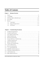 6
6 -
 7
7 -
8
-
9
-
10
-
11
-
12
-
13
-
14
-
15
-
16
-
17
-
18
-
19
-
20
-
21
-
22
-
23
-
24
-
25
-
26
-
27
-
28
-
29
-
30
-
31
-
32
-
33
-
34
-
35
-
36
-
37
-
38
-
39
-
40
-
41
-
42
-
43
-
44
-
45
-
46
-
47
-
48
-
49
-
50
-
51
-
52
-
53
-
54
-
55
-
56
-
57
-
58
-
59
-
60
-
61
-
62
-
63
-
64
-
65
-
66
-
67
-
68
-
69
-
70
-
71
-
72
-
73
-
74
-
75
-
76
-
77
-
78
-
79
-
80
-
81
-
82
-
83
-
84
-
85
-
86
-
87
-
88
-
89
-
90
-
91
-
92
-
93
-
94
-
95
-
96
-
97
-
98
-
99
-
100
-
101
-
102
-
103
-
104
-
105
-
106
-
107
-
108
-
109
-
110
-
111
-
112
-
113
-
114
-
115
-
116
-
117
-
118
-
119
-
120
-
121
-
122
-
123
-
124
-
125
-
126
-
127
-
128
-
129
-
130
-
131
-
132
-
133
-
134
-
135
-
136
-
137
-
138
-
139
-
140
-
141
-
142
-
143
-
144
-
145
-
146
-
147
-
148
-
149
-
150
-
151
-
152
-
153
-
154
-
155
-
156
-
157
-
158
-
159
-
160
-
161
-
162
-
163
-
164
-
165
-
166
-
167
-
168
-
169
-
170
-
171
-
172
-
173
-
174
-
175
-
176
-
177
-
178
-
179
-
180
-
181
-
182
-
183
-
184
-
185
-
186
-
187
-
188
-
189
-
190
-
191
-
192
-
193
-
194
-
195
-
196
-
197
-
198
-
199
-
200
-
201
-
202
-
203
-
204
-
205
-
206
-
207
-
208
-
209
-
210
-
211
-
212
-
213
-
214
-
215
-
216
-
217
-
218
-
219
-
220
-
221
-
222
-
223
-
224
-
225
-
226
-
227
-
228
-
229
-
230
-
231
-
232
-
233
-
234
-
235
-
236
-
237
-
238
-
239
-
240
-
241
-
242
-
243
-
244
-
245
-
246
-
247
-
248
-
249
-
250
-
251
-
252
-
253
-
254
-
255
-
256
-
257
-
258
-
259
-
260
-
261
-
262
-
263
-
264
-
265
-
266
-
267
-
268
-
269
-
270
-
271
-
272
-
273
-
274
-
275
-
276
-
277
-
278
-
279
-
280
-
281
-
282
-
283
-
284
-
285
-
286
-
287
-
288
-
289
-
290
-
291
-
292
-
293
-
294
-
295
-
296
-
297
-
298
-
299
-
300
-
301
 |
 |

Toshiba Personal Computer
Satellite & Satellite Pro
Maintenance Manual
TOSHIBA CORPORATION