Toshiba Satellite A660-BT3G25X Maintenance Manual - Page 177
Keyboard Cover & Keyboard
 |
View all Toshiba Satellite A660-BT3G25X manuals
Add to My Manuals
Save this manual to your list of manuals |
Page 177 highlights
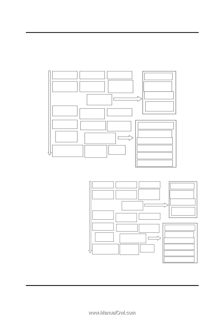
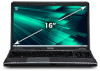
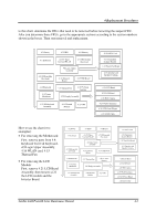
4 Replacement Procedures to this chart, determine the FRUs that need to be removed before removing the suspect FRU. After you determine those FRUs, go to the appropriate sections according to the section numbers shown in the boxes. Then start removal and replacement. 4.2 Battery 4.3 HDD 4.4 Memory 4.5 Keyboard 4.9 ODD module (Slot-load) 4.16 Bluetooth 4.19 Power Membrane 4.6 TV Tuner Card and WLAN 4.7 ODD module (Tray-load) 4.8 Logic Upper Assembly 4.14 Indicator Board 4.15 USB Board 4.17 Thermal Fan 4.18 TV Tuner Antenna 4.20 Display Assembly 4.21 Motherboard Assembly 4.22 Thermal Module 4.23 CPU 4.10 FeliCa Card 4.11 Fingerprint Scanner Bracket 4.12 Touch Pad Board 4.13 Speakers and Speaker Cushions 4.24 LCD Bezel 4.25 LCD Panel 4.26 Web Camera 4.27 WLAN Antennas 4.28 LCD Panel Hinges 4.29 LVDS Cable How to use the chart (two examples): • For removing the Motheroard: First, remove parts from 4.8 Keyboard Cover & Keyboard, 4.9 Logic Upper Assembly, 4.16 WLAN card, 4.15 Thermal Fan. • For removing the LCD Module: First, remove 4.21 LCD Bezel Assembly, then remove 4.22 the LCD module and the Inverter Board. 4.2 Battery 4.3 HDD 4.4 Memory 4.5 Keyboard 4.9 ODD module (Slot-load) 4.16 Bluetooth 4.19 Power Membrane 4.6 TV Tuner Card and WLAN 4.7 ODD module (Tray-load) 4.8 Logic Upper Assembly 4.14 Indicator Board 4.15 USB Board 4.17 Thermal Fan 4.18 TV Tuner Antenna 4.20 Display Assembly 4.21 Motherboard Assembly 4.22 Thermal Module 4.23 CPU 4.10 FeliCa Card 4.11 Fingerprint Scanner Bracket 4.12 Touch Pad Board 4.13 Speakers and Speaker Cushions 4.24 LCD Bezel 4.25 LCD Panel 4.26 Web Camera 4.27 WLAN Antennas 4.28 LCD Panel Hinges 4.29 LVDS Cable Satellite A660/ProA660 Series Maintenance Manual 4-2
-
 1
1 -
2
-
3
-
4
-
5
-
6
-
7
-
8
-
9
-
10
-
11
-
12
-
13
-
14
-
15
-
16
-
17
-
18
-
19
-
20
-
21
-
22
-
23
-
24
-
25
-
26
-
27
-
28
-
29
-
30
-
31
-
32
-
33
-
34
-
35
-
36
-
37
-
38
-
39
-
40
-
41
-
42
-
43
-
44
-
45
-
46
-
47
-
48
-
49
-
50
-
51
-
52
-
53
-
54
-
55
-
56
-
57
-
58
-
59
-
60
-
61
-
62
-
63
-
64
-
65
-
66
-
67
-
68
-
69
-
70
-
71
-
72
-
73
-
74
-
75
-
76
-
77
-
78
-
79
-
80
-
81
-
82
-
83
-
84
-
85
-
86
-
87
-
88
-
89
-
90
-
91
-
92
-
93
-
94
-
95
-
96
-
97
-
98
-
99
-
100
-
101
-
102
-
103
-
104
-
105
-
106
-
107
-
108
-
109
-
110
-
111
-
112
-
113
-
114
-
115
-
116
-
117
-
118
-
119
-
120
-
121
-
122
-
123
-
124
-
125
-
126
-
127
-
128
-
129
-
130
-
131
-
132
-
133
-
134
-
135
-
136
-
137
-
138
-
139
-
140
-
141
-
142
-
143
-
144
-
145
-
146
-
147
-
148
-
149
-
150
-
151
-
152
-
153
-
154
-
155
-
156
-
157
-
158
-
159
-
160
-
161
-
162
-
163
-
164
-
165
-
166
-
167
-
168
-
169
-
170
-
171
-
 172
172 -
 173
173 -
 174
174 -
 175
175 -
 176
176 -
 177
177 -
 178
178 -
 179
179 -
 180
180 -
 181
181 -
 182
182 -
183
-
184
-
185
-
186
-
187
-
188
-
189
-
190
-
191
-
192
-
193
-
194
-
195
-
196
-
197
-
198
-
199
-
200
-
201
-
202
-
203
-
204
-
205
-
206
-
207
-
208
-
209
-
210
-
211
-
212
-
213
-
214
-
215
-
216
-
217
-
218
-
219
-
220
-
221
-
222
-
223
-
224
-
225
-
226
-
227
-
228
-
229
-
230
-
231
-
232
-
233
-
234
-
235
-
236
-
237
-
238
-
239
-
240
-
241
-
242
-
243
-
244
-
245
-
246
-
247
-
248
-
249
-
250
-
251
-
252
-
253
-
254
-
255
-
256
-
257
-
258
-
259
-
260
-
261
-
262
-
263
-
264
-
265
-
266
-
267
-
268
-
269
-
270
-
271
-
272
-
273
-
274
-
275
-
276
-
277
-
278
-
279
-
280
-
281
-
282
-
283
-
284
-
285
-
286
-
287
-
288
-
289
-
290
-
291
-
292
-
293
-
294
-
295
-
296
-
297
-
298
-
299
-
300
-
301
 |
 |