Toshiba Satellite A660-BT3G25X Maintenance Manual - Page 204
ODD Module Slot-load
 |
View all Toshiba Satellite A660-BT3G25X manuals
Add to My Manuals
Save this manual to your list of manuals |
Page 204 highlights
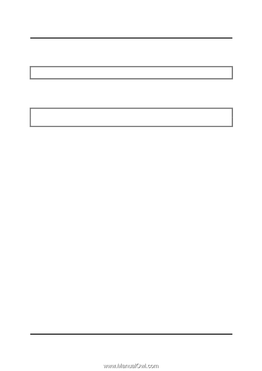
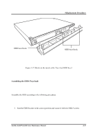
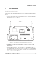
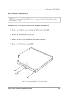
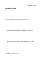
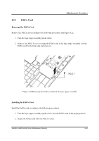
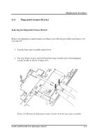
4.9 ODD Module (Slot-load) 4 Replacement Procedures CAUTION: Handle the ODD module carefully. It can become hot during operation. Removing the ODD Module (Slot-load) Remove the ODD (optical disc drive) module according to the following procedures. NOTE: Do not disassemble the ODD drive when it is working normally. Disassemble or replace the ODD drive only if it fails. 1. Remove the logic upper assembly from the system. 2. Lift and remove the ODD frame (straight up) from the logic lower assembly. 3. Push the ODD outward (into the empty space left by the ODD frame) to release it from the connector on the motherboard. 4. Lift and remove the ODD (straight up) from the logic lower assembly. 5. Carefully push the ODD button (eject button) outward and away from the logic lower assembly, then remove. Installing the ODD Module (Slot-load) Install the ODD module according to the following procedures. 1. Replace the motherboard. 2. Place the ODD into the logic lower assembly (straight down) and slid it inward to connect with the motherboard. 3. Place the ODD frame into the space between the ODD and the right edge of the logic lower assembly. 4. Align the ODD button (eject button) with (the outside of) the logic lower assembly and carefully push it inward to secure it in place the ODD into the ODD bay. 5. Slide the ODD inward until it meets the end. Satellite A660/ProA660 Series Maintenance Manual 4-29
-
 1
1 -
2
-
3
-
4
-
5
-
6
-
7
-
8
-
9
-
10
-
11
-
12
-
13
-
14
-
15
-
16
-
17
-
18
-
19
-
20
-
21
-
22
-
23
-
24
-
25
-
26
-
27
-
28
-
29
-
30
-
31
-
32
-
33
-
34
-
35
-
36
-
37
-
38
-
39
-
40
-
41
-
42
-
43
-
44
-
45
-
46
-
47
-
48
-
49
-
50
-
51
-
52
-
53
-
54
-
55
-
56
-
57
-
58
-
59
-
60
-
61
-
62
-
63
-
64
-
65
-
66
-
67
-
68
-
69
-
70
-
71
-
72
-
73
-
74
-
75
-
76
-
77
-
78
-
79
-
80
-
81
-
82
-
83
-
84
-
85
-
86
-
87
-
88
-
89
-
90
-
91
-
92
-
93
-
94
-
95
-
96
-
97
-
98
-
99
-
100
-
101
-
102
-
103
-
104
-
105
-
106
-
107
-
108
-
109
-
110
-
111
-
112
-
113
-
114
-
115
-
116
-
117
-
118
-
119
-
120
-
121
-
122
-
123
-
124
-
125
-
126
-
127
-
128
-
129
-
130
-
131
-
132
-
133
-
134
-
135
-
136
-
137
-
138
-
139
-
140
-
141
-
142
-
143
-
144
-
145
-
146
-
147
-
148
-
149
-
150
-
151
-
152
-
153
-
154
-
155
-
156
-
157
-
158
-
159
-
160
-
161
-
162
-
163
-
164
-
165
-
166
-
167
-
168
-
169
-
170
-
171
-
172
-
173
-
174
-
175
-
176
-
177
-
178
-
179
-
180
-
181
-
182
-
183
-
184
-
185
-
186
-
187
-
188
-
189
-
190
-
191
-
192
-
193
-
194
-
195
-
196
-
197
-
198
-
 199
199 -
 200
200 -
 201
201 -
 202
202 -
 203
203 -
 204
204 -
 205
205 -
 206
206 -
 207
207 -
 208
208 -
 209
209 -
210
-
211
-
212
-
213
-
214
-
215
-
216
-
217
-
218
-
219
-
220
-
221
-
222
-
223
-
224
-
225
-
226
-
227
-
228
-
229
-
230
-
231
-
232
-
233
-
234
-
235
-
236
-
237
-
238
-
239
-
240
-
241
-
242
-
243
-
244
-
245
-
246
-
247
-
248
-
249
-
250
-
251
-
252
-
253
-
254
-
255
-
256
-
257
-
258
-
259
-
260
-
261
-
262
-
263
-
264
-
265
-
266
-
267
-
268
-
269
-
270
-
271
-
272
-
273
-
274
-
275
-
276
-
277
-
278
-
279
-
280
-
281
-
282
-
283
-
284
-
285
-
286
-
287
-
288
-
289
-
290
-
291
-
292
-
293
-
294
-
295
-
296
-
297
-
298
-
299
-
300
-
301
 |
 |