Yamaha AW16G Owner's Manual - Page 160
Digital input settings/Checking and initializing the internal hard disk - owners manual
 |
View all Yamaha AW16G manuals
Add to My Manuals
Save this manual to your list of manuals |
Page 160 highlights
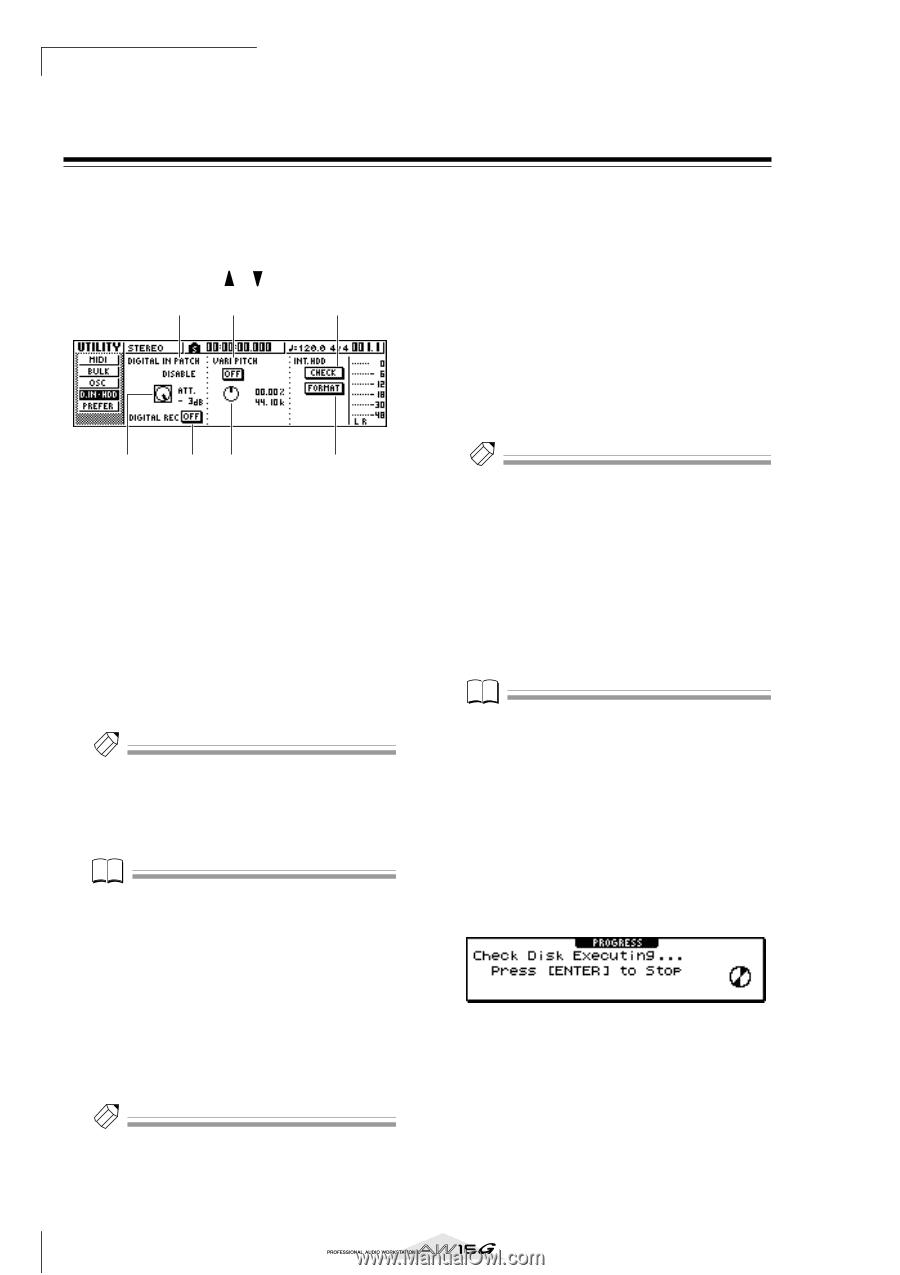
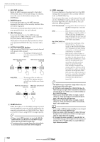
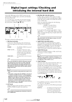
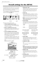
MIDI and utility functions Digital input settings/Checking and initializing the internal hard disk In the D.IN HDD page of the UTILITY screen you can make settings for digital input, and check and initialize the internal hard disk. To access this page, repeatedly press the Work Navigation section [UTILITY] key or hold down the [UTILITY] key and use the CURSOR [ ]/[ ] keys. 14 6 2 35 7 This page contains the following items. 1 DIGITAL IN PATCH Selects one of the following as the destination to which the signal from the DIGITAL IN jack will be sent. DISABLE The DIGITAL STEREO IN jack will be disabled. INPUT 1/2-7/8 .......... The signal will be sent to input channels 1/2-7/8. If you select this setting, the MIC/LINE input jacks for the corresponding input channels will be disabled. STEREO BUS The signal will be sent to the stereo bus. Tip! If you select DISABLE, the AW16G will operate using its own internal clock. If you select any other setting, the AW16G will synchronize to the clock contained in the input signal from the DIGITAL STEREO IN jack. However when playing an audio CD, the AW16G always operates using its own clock. Note • You cannot switch this setting while the recorder is running. • If you select a setting other than DISABLE, a message of "((((WRONG WORD CLOCK!!))))" will be displayed if appropriate clock data is not being sent to the DIGITAL STEREO IN jack. While this message is displayed, all channels will be muted and the recorder section will not operate. To make the AW16G operate, you must either input the correct clock signal or switch the DIGITAL IN PATCH setting to DISABLE. B ATT knob Adjusts the level of the signal that is sent from the DIGITAL STEREO IN jack to the stereo bus. Tip! The ATT knob is meaningful only if DIGITAL IN PATCH is set to STEREO BUS. C DIGITAL REC ON/OFF button Enables (ON) or disables (OFF) digital recording from the DIGITAL IN jack, and importing of digital audio data from an audio CD or WAV file inserted in the CD-RW drive. When you switch this setting ON, the following message will be displayed. OBSERVE Copyright Notice Written in Owner's Manual? [Cancel] [OK] If you agree to the conditions described in "Copyright Notice" (→ p. 5), select [OK]. When you select [OK], recording and importing of digital audio data will be enabled. Tip! The DIGITAL REC ON/OFF button is always set to OFF when you turn on the power. D VARI PITCH ON/OFF button Selects whether the sampling frequency will be adjustable (Vari-pitch function) when DIGITAL IN PATCH is set to DISABLE. If you turn this button on, vari-pitch will be enabled, and you can use the VARI PITCH knob to adjust the sampling frequency. E VARI PITCH knob Adjusts the sampling frequency of the current song in a range of -5.97 to +6.00%. Note Vari-pitch is not available if DIGITAL IN PATCH is set to other than DISABLE, or if you have selected MTC Slave in the MIDI page of the UTILITY screen. F CHECK button Checks the state of the internal hard disk. When you move the cursor to this button and press the [ENTER] key, a popup window will ask you for confirmation. If you move the cursor to the OK button and press the [ENTER] key, the current song will be saved automatically, and the check will be executed. A popup window will appear while checking is in progress, but you can abort the check by pressing the [ENTER] key. If no problems are found, a popup window indicating "No Error" will appear. If a problem is found, one of the following messages will appear. Read Error The display will indicate the num- ber of locations for which data could not be read from the hard disk. It is possible that the hard disk has been physically damaged. 160
-
 1
1 -
2
-
3
-
4
-
5
-
6
-
7
-
8
-
9
-
10
-
11
-
12
-
13
-
14
-
15
-
16
-
17
-
18
-
19
-
20
-
21
-
22
-
23
-
24
-
25
-
26
-
27
-
28
-
29
-
30
-
31
-
32
-
33
-
34
-
35
-
36
-
37
-
38
-
39
-
40
-
41
-
42
-
43
-
44
-
45
-
46
-
47
-
48
-
49
-
50
-
51
-
52
-
53
-
54
-
55
-
56
-
57
-
58
-
59
-
60
-
61
-
62
-
63
-
64
-
65
-
66
-
67
-
68
-
69
-
70
-
71
-
72
-
73
-
74
-
75
-
76
-
77
-
78
-
79
-
80
-
81
-
82
-
83
-
84
-
85
-
86
-
87
-
88
-
89
-
90
-
91
-
92
-
93
-
94
-
95
-
96
-
97
-
98
-
99
-
100
-
101
-
102
-
103
-
104
-
105
-
106
-
107
-
108
-
109
-
110
-
111
-
112
-
113
-
114
-
115
-
116
-
117
-
118
-
119
-
120
-
121
-
122
-
123
-
124
-
125
-
126
-
127
-
128
-
129
-
130
-
131
-
132
-
133
-
134
-
135
-
136
-
137
-
138
-
139
-
140
-
141
-
142
-
143
-
144
-
145
-
146
-
147
-
148
-
149
-
150
-
151
-
152
-
153
-
154
-
 155
155 -
 156
156 -
 157
157 -
 158
158 -
 159
159 -
 160
160 -
 161
161 -
 162
162 -
 163
163 -
 164
164 -
 165
165 -
166
-
167
-
168
-
169
-
170
-
171
-
172
-
173
-
174
-
175
-
176
-
177
-
178
-
179
-
180
-
181
-
182
-
183
-
184
-
185
-
186
-
187
-
188
-
189
-
190
-
191
-
192
-
193
-
194
-
195
-
196
-
197
-
198
-
199
-
200
-
201
-
202
-
203
-
204
-
205
-
206
-
207
-
208
-
209
-
210
-
211
-
212
-
213
-
214
-
215
-
216
-
217
-
218
-
219
 |
 |