Yamaha DSP-AX1 Owner's Manual - Page 18
Connecting Audio Components
 |
View all Yamaha DSP-AX1 manuals
Add to My Manuals
Save this manual to your list of manuals |
Page 18 highlights
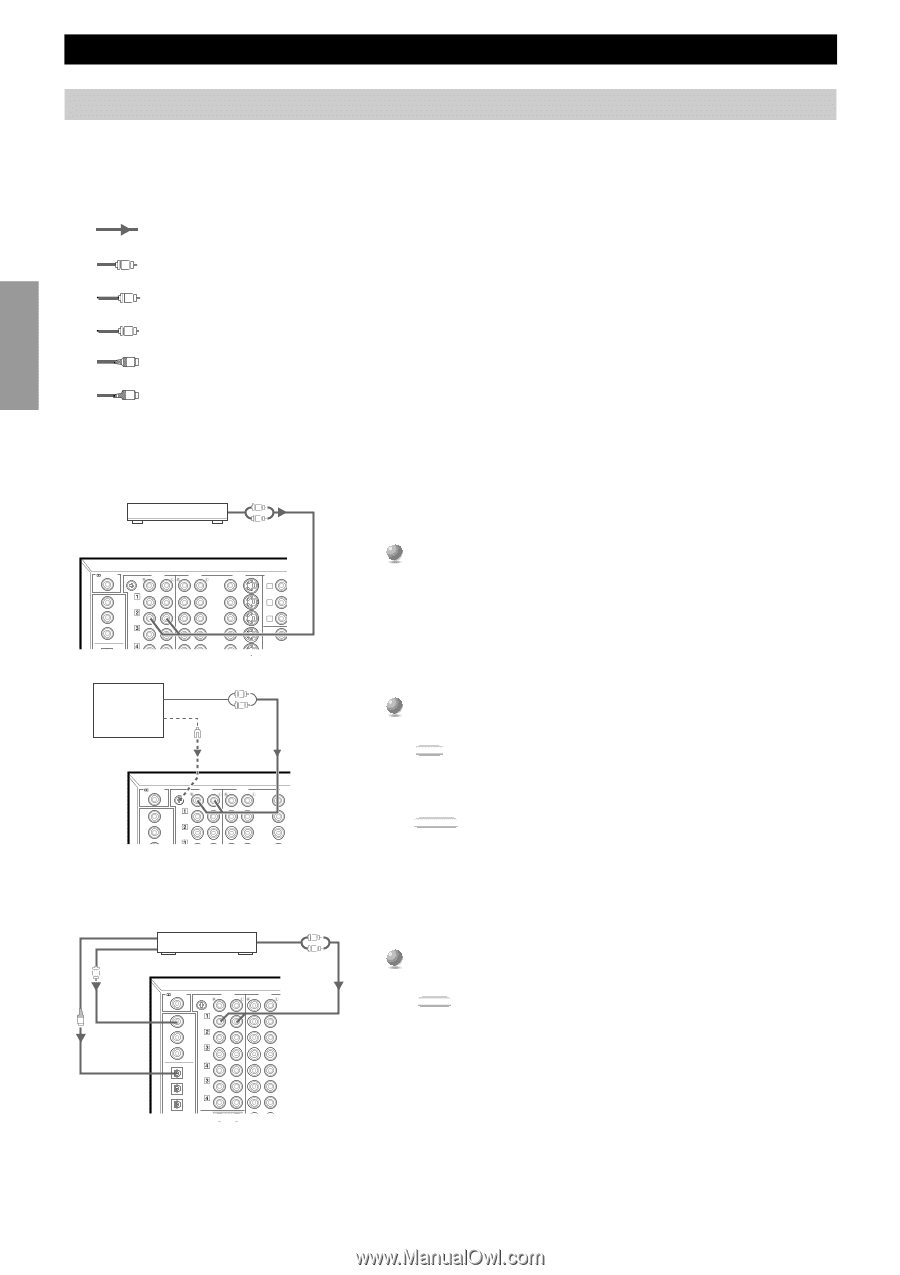
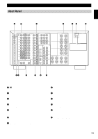
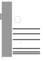
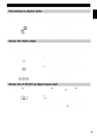
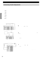
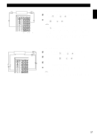
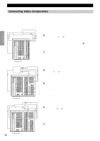
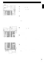
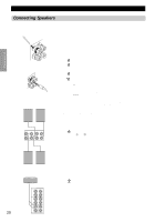
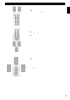
Preparations Hookups Connecting Audio Components Before you connect any components, disconnect the power supply to all the components you plan to connect including the DSP-AX1 and determine which jacks are for the left and right channels and for input and output. When you connect other YAMAHA audio equipment (such as a CD player or changer, Tuner, MD deck, or tape deck), connect to terminals with the same number labels. Yamaha applies this labelling system to all its products. In the hookup illustrations on the following pages: indicates signal direction, C indicates coaxial cables, L indicates left side analog cables, R indicates right side analog cables, O indicates optical cables; and, S indicates S-video cables. After you finish all hookups, check them again to make sure they are correct. AM/FM Tuner Audio Output L R s Connecting an AM/FM Tuner RF(AC-3) LD GND AUDIO PHONO CD CD DVD TUNER COAXIAL OPTICAL CBL /SAT CD IN (PLAY) TAPE OUT (REC) AUDIO VIDEO DVD VIDEO S VIDEO LD D-TV CBL /SAT IN COMPONENT VIDEO Y PB/CB PR/ A B C M PREOUT/MAIN Output L Turntable Ground R RF(AC-3) LD GND AUDIO PHONO CD CD DVD TUNER CBL /SAT IN (PLAY) AUDIO VIDEO DVD VIDEO S VIDEO LD D-TV CBL /SAT 1 Connect the left and right signal output jacks on your tuner to the TUNER 2 L and R jacks. s Connecting a Turntable 1 Connect the left and right signal output cords to the PHONO L and R jacks. Note: • These jacks are for connecting a turntable with an MM or high output MC cartridge. If you have a turntable with a low output MC cartridge, use an inline boosting transformer or MC-head amplifier when connecting to these jacks. Caution: • The GND terminal does not electrically ground the turntable. It simply reduces noise in the signal. In some cases, you may hear less noise if you do not connect to the GND terminal. Optical Output CD Player Coaxial Output C RF(AC-3) LD GND AUDIO PHONO O CD CD DVD TUNER COAXIAL OPTICAL CBL /SAT CD IN (PLAY) TAPE OUT (REC) IN (PLAY) MD OUT (REC) IN (PLAY) MD OUT (REC) DVD MAIN Analog Output L R AUDIO VIDEO DVD VIDEO S VIDEO LD D-TV CBL /SAT IN VCR 1 OUT IN VCR 2 OUT s Connecting a CD Player 1 Connect the left and right analog signal output jacks on your CD player to the CD 1 L and R jacks. COMPONEN Y P A Notes: B • The COAXIAL CD and OPTICAL CD jacks are available for a CD player which C has coaxial or optical digital outputs. • When you connect a CD player to both the COAXIAL CD and OPTICAL CD jacks, priority is given to the input signals from the COAXIAL CD jack. • The OPTICAL jacks on this unit conform to the EIA standard. If you use a fiber IN REMOTE 1 optic cable that does not conform to this standard, the DSP-AX1 may not function OUT properly. 16
-
 1
1 -
2
-
3
-
4
-
5
-
6
-
7
-
8
-
9
-
10
-
11
-
12
-
 13
13 -
 14
14 -
 15
15 -
 16
16 -
 17
17 -
 18
18 -
 19
19 -
 20
20 -
 21
21 -
 22
22 -
 23
23 -
24
-
25
-
26
-
27
-
28
-
29
-
30
-
31
-
32
-
33
-
34
-
35
-
36
-
37
-
38
-
39
-
40
-
41
-
42
-
43
-
44
-
45
-
46
-
47
-
48
-
49
-
50
-
51
-
52
-
53
-
54
-
55
-
56
-
57
-
58
-
59
-
60
-
61
-
62
-
63
-
64
-
65
-
66
-
67
-
68
-
69
-
70
-
71
-
72
-
73
-
74
-
75
-
76
-
77
-
78
-
79
-
80
-
81
-
82
-
83
-
84
-
85
-
86
-
87
-
88
 |
 |