Yamaha DSP-AX1 Owner's Manual - Page 20
Connecting Video Components, Connecting an LD Player, Connecting a TV or Digital TV
 |
View all Yamaha DSP-AX1 manuals
Add to My Manuals
Save this manual to your list of manuals |
Page 20 highlights
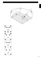
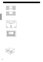
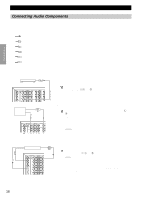
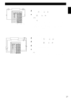
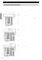
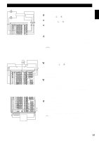
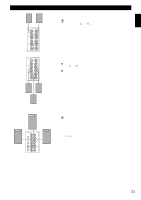
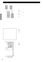
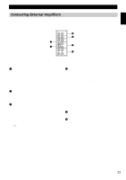
Hookups Preparations Connecting Video Components Before you connect any components, disconnect the power supply to all the components you plan to connect including the DSP-AX1 and determine which jacks are for the left and right channels and for input and output. After you finish all hookups, check them again to make sure they are correct. Note: • If you make S-video connections to this unit, it is not necessary to make composite video connections. If both types of connections are made, this unit gives priority to the S-video signal. Optical Output S-video Output Video Output LD Player L RF-Signal O C Output Analog Audio R Output C S RF(AC-3) LD GND AUDIO PHONO AUDIO VIDEO DVD VIDEO S VIDEO CD CD LD DVD TUNER COAXIAL OPTICAL CBL /SAT CD IN (PLAY) TAPE OUT (REC) IN (PLAY) MD OUT (REC) IN (PLAY) MD OUT (REC) DVD MAIN LD SURROUND D-TV CBL /SAT SUB WOOFER 6CH INPUT CENTER ZONE 2 OUT VCR 1 DIGITAL D-TV CBL /SAT IN VCR 1 OUT IN VCR 2 OUT IN VCR 3 OUT MONITOR VIDEO OUT 1 OUT MONITOR OUT 2 COMPONENT VIDEO Y PB/CB A B C PR/CR DVD D-TV CBL /SAT MONITOR OUT PREOUT/MAIN IN IN REMOTE 1 OUT REMOTE 2 IN MONO RB- REAR CTR 2320 RS 232C CTRL OUT +5V 100Ω 20mA FRONT REAR (SURROUND) SUB WOOFER SPLIT CENTER IN CENTER OUT MAIN IN MAIN OUT s Connecting an LD Player 1 Connect the left and right audio signal output jacks on your LD player to the LD L and R jacks. If your LD player has an RF signal or optical digital signal outputs, you can connect them to this unit. Connect the RF signal output jack on your LD player to the RF (AC-3) LD jack. Connect the optical digital signal output jack on your LD player to the OPTICAL LD jack. 2 Connect the composite video signal output jack on your LD player to the LD VIDEO jack. If your LD player has an S-video output, you can connect it to this unit. Connect the S-video signal output jack on your LD player to the LD S VIDEO jack. Optical Output O Digital TV/ TV Analog Audio Output L R S-video Output Component C Video Output Output S RF(AC-3) LD GND AUDIO PHONO AUDIO VIDEO DVD VIDEO S VIDEO COMPONENT VIDEO Y PB/CB A PR/CR DVD CD CD LD B D-TV DVD TUNER COAXIAL OPTICAL CBL /SAT CD IN (PLAY) TAPE OUT (REC) IN (PLAY) MD OUT (REC) IN (PLAY) MD OUT (REC) DVD MAIN LD SURROUND D-TV CBL /SAT SUB WOOFER 6CH INPUT CENTER ZONE 2 OUT VCR 1 DIGITAL D-TV CBL /SAT IN VCR 1 OUT IN VCR 2 OUT IN VCR 3 OUT MONITOR VIDEO OUT 1 OUT MONITOR OUT 2 C CBL /SAT MONITOR OUT PREOUT/MAIN IN FRONT IN REMOTE 1 REAR (SURROUND) OUT REMOTE 2 MONO SUB WOOFER SPLIT IN CENTER IN B RB- REAR CTR 2320 CENTER OUT + RS 232C CTRL OUT +5V 100Ω 20mA MAIN IN - MAIN OUT s Connecting a TV or Digital TV 1 Connect the left and right analog signal output jacks on your TV to the D-TV L and R jacks. If your TV has an optical digital signal output, you can connect it to this unit. Connect the optical digital signal output jack on your TV to the OPTICAL D-TV jack. 2 Connect the composite video signal output jack on your TV to the D-TV VIDEO jack. If your TV has an S-video output or component video output, you can connect it to this unit. Connect the S-video signal output jack on your TV to the D-TV S VIDEO jack or connect the component signal output jacks on your TV to the D-TV COMPONENT VIDEO jacks. L R Optical Output Satellite/Cable TV Tuner Coaxial Output O C C Video Output RF(AC-3) LD GND AUDIO PHONO AUDIO VIDEO DVD VIDEO S VIDEO CD CD LD DVD TUNER COAXIAL OPTICAL CBL /SAT CD IN (PLAY) TAPE OUT (REC) IN (PLAY) MD OUT (REC) IN (PLAY) MD OUT (REC) DVD MAIN LD SURROUND D-TV CBL /SAT SUB WOOFER 6CH INPUT CENTER ZONE 2 OUT VCR 1 DIGITAL D-TV CBL /SAT IN VCR 1 OUT IN VCR 2 OUT IN VCR 3 OUT MONITOR VIDEO OUT 1 OUT MONITOR OUT 2 18 Analog Audio Output S-video Output Component Output S COMPONENT VIDEO Y PB/CB A B C PR/CR DVD D-TV CBL /SAT MONITOR OUT PREOUT/MAIN IN FRONT IN REMOTE 1 REAR (SURROUND) OUT REMOTE 2 MONO SUB WOOFER SPLIT IN CENTER IN B RB- REAR CTR 2320 CENTER OUT + RS 232C CTRL OUT +5V 100Ω 20mA MAIN IN - MAIN OUT s Connecting a Satellite Tuner or Cable TV Tuner (Set Top Box) 1 Connect the left and right audio signal output jacks on your tuner to the CBL/SAT L and R jacks. S If your tuner has coaxial or optical digital signal outputs, you can connect them to this unit. Connect the coaxial digital signal output jack on your tuner to the COAXIAL CBL/SAT jack. Connect the optical digital signal output jack on your tuner to the OPTICAL CBL/SAT jack. 2 Connect the composite video signal output jack on your tuner to the CBL/SAT VIDEO jack. If your tuner has an S-video or component video output, you can connect it to this unit. Connect the S-video signal output jack on your tuner to the CBL/SAT S VIDEO jack or connect the component signal output jacks on your tuner to the CBL/SAT COMPONENT VIDEO jacks.
-
 1
1 -
2
-
3
-
4
-
5
-
6
-
7
-
8
-
9
-
10
-
11
-
12
-
13
-
14
-
 15
15 -
 16
16 -
 17
17 -
 18
18 -
 19
19 -
 20
20 -
 21
21 -
 22
22 -
 23
23 -
 24
24 -
 25
25 -
26
-
27
-
28
-
29
-
30
-
31
-
32
-
33
-
34
-
35
-
36
-
37
-
38
-
39
-
40
-
41
-
42
-
43
-
44
-
45
-
46
-
47
-
48
-
49
-
50
-
51
-
52
-
53
-
54
-
55
-
56
-
57
-
58
-
59
-
60
-
61
-
62
-
63
-
64
-
65
-
66
-
67
-
68
-
69
-
70
-
71
-
72
-
73
-
74
-
75
-
76
-
77
-
78
-
79
-
80
-
81
-
82
-
83
-
84
-
85
-
86
-
87
-
88
 |
 |
