Yamaha DTX450K Owner's Manual - Page 14
For DTX430K Owners, For DTX450K Owners
 |
View all Yamaha DTX450K manuals
Add to My Manuals
Save this manual to your list of manuals |
Page 14 highlights
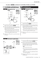
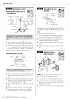
Assembly Guide The details of Step 7 are different for the DTX400K, DTX430K, and DTX450K. For DTX430K Owners Step 7 Attaching the snare pad 1. Loosen the wing bolt on the joint on the left arm, which was attached in Step 4 . Left arm For DTX450K Owners Step 7 Attaching the snare pad 1. Loosen the wing bolt on the joint on the left arm, which was attached in Step 4 . Left arm Wing bolt 90° Joint 2. Rotate the joint 90° counter-clockwise, making the joint section horizontal. 3. Securely tighten the wing bolt. 4. Loosen the key bolt on the joint. Wing bolt 90° Joint 2. Rotate the joint 90° counter-clockwise, making the joint section horizontal. 3. Securely tighten the wing bolt. 4. Loosen the key bolt on the joint. u 5. Take the snare pad (i) from the package and slide it fully into the joint. i 6. Tighten the key bolt to secure the snare pad (i) in place. 5. Take the hexagonal rod (u) from the package and slide it fully into the joint. 6. Tighten the key bolt to secure the hexagonal rod (u) in place. 7. Take the snare pad (i) and the S wing bolt (o) from the package and lightly tighten the S wing bolt (o). (Five or six turns is sufficient.) o i i 14 DTX400K/DTX430K/DTX450K Owner's Manual 8. Place the snare pad (i) on the hexagonal rod (u), which was attached in 6. above, and slide it fully back. Then tighten the S wing bolt (o) to secure the snare pad (i) in place. u i o 9. Loosen the key bolt and adjust the angle of the snare pad. When finished, retighten the key bolt to secure the snare pad in place.
-
 1
1 -
2
-
3
-
4
-
5
-
6
-
7
-
8
-
 9
9 -
 10
10 -
 11
11 -
 12
12 -
 13
13 -
 14
14 -
 15
15 -
 16
16 -
 17
17 -
 18
18 -
 19
19 -
20
-
21
-
22
-
23
-
24
-
25
-
26
-
27
-
28
-
29
-
30
-
31
-
32
-
33
-
34
-
35
-
36
-
37
-
38
-
39
-
40
-
41
-
42
-
43
-
44
-
45
-
46
-
47
-
48
-
49
-
50
-
51
-
52
-
53
-
54
-
55
-
56
-
57
-
58
-
59
-
60
-
61
-
62
-
63
-
64
-
65
-
66
-
67
-
68
 |
 |
