Yamaha DTX450K Owner's Manual - Page 15
For DTX400K and DTX430K Owners, For DTX450K Owners - tips
 |
View all Yamaha DTX450K manuals
Add to My Manuals
Save this manual to your list of manuals |
Page 15 highlights
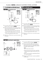
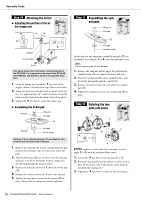
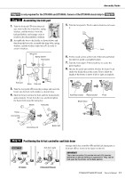
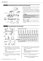
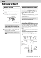
Assembly Guide The details of Step 8 are different for the DTX400K, DTX430K, and DTX450K. For DTX400K and DTX430K Owners Step 8 Attaching the hi-hat holder For DTX450K Owners Step 8 Attaching the hi-hat holder !1 Left arm Snare pad !1 Joint Joint 1. Loosen the two key bolts on the joint on the snare- pad part, which was attached in Step 7 . 2. Take the hi-hat holder (!1) from the package and slide it into the joint from the front as shown in the figure. Then adjust the angle of the hi-hat holder. • When correctly inserted, the tip of the hi-hat holder (!1) will protrude slightly from the rear of the joint. • When correctly oriented, the metal rod section at the top of the hi-hat holder (!1) will be vertical. 3. Tighten the two key bolts to secure the hi-hat holder (!1) in place. 1. Loosen the two key bolts on the joint on the left arm, which was attached in Step 4 . 2. Take the hi-hat holder (!1) from the package and slide it into the joint from the rear as shown in the figure. Then adjust the angle of the hi-hat holder. • When correctly inserted, the tip of the hi-hat holder (!1) will protrude slightly from the front of the joint. • When correctly oriented, the metal rod section at the top of the hi-hat holder (!1) will be vertical. 3. Tighten the two key bolts to secure the hi-hat holder (!1) in place. Step 9 Attaching the cymbal holders !0 !0 1. Loosen the four key bolts at the ends of the first/sec- ond tom part, which was attached in Step 6 . 2. Take the cymbal holders (!0) from the package and insert them into the ends of the first/second tom part. Then adjust the angles of the cymbal holders until they are oriented as shown in the figure. NOTE The two cymbal holders are identical. • When correctly inserted, the tips of the cymbal hold- ers (!0) will protrude slightly from the bottom of the tom part. • When correctly oriented, the cymbal holders (!0) will be as shown in the figure. 3. Tighten the four key bolts to secure the cymbal hold- ers (!0) in place. DTX400K/DTX430K/DTX450K Owner's Manual 15
-
 1
1 -
2
-
3
-
4
-
5
-
6
-
7
-
8
-
9
-
 10
10 -
 11
11 -
 12
12 -
 13
13 -
 14
14 -
 15
15 -
 16
16 -
 17
17 -
 18
18 -
 19
19 -
 20
20 -
21
-
22
-
23
-
24
-
25
-
26
-
27
-
28
-
29
-
30
-
31
-
32
-
33
-
34
-
35
-
36
-
37
-
38
-
39
-
40
-
41
-
42
-
43
-
44
-
45
-
46
-
47
-
48
-
49
-
50
-
51
-
52
-
53
-
54
-
55
-
56
-
57
-
58
-
59
-
60
-
61
-
62
-
63
-
64
-
65
-
66
-
67
-
68
 |
 |
