Yamaha MD4 Owner's Manual - Page 12
Input Channels, GAIN control, EQ controls, GROUP ASSIGN switches, Input source selector switch, Fader - md4s
 |
View all Yamaha MD4 manuals
Add to My Manuals
Save this manual to your list of manuals |
Page 12 highlights
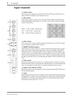
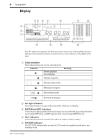
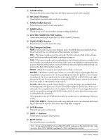
4 Touring MD4 Input Channels 1 1 GAIN LINE MIC HIGH -12 +12 MID 2 -12 +12 LOW 3 4 -12 +12 AUX 0 10 1 2 GROUP ASSIGN 3 4 PAN 5 L ODD 6 PB R EVEN MIC/ LINE 10 9 8 7 76 5 4 3 2 1 0 1 GAIN control This rotary control adjusts the sensitivity of the MIC/LINE input so that both microphone and line-level signals can be handled with ease. 2 EQ controls These rotary controls are used to boost and cut the high, middle, and low frequency bands independently. A flat setting (i.e., no boost or cut) can be set quickly using the control's center detent. 15 10 Response (dB) HIGH ±12 dB at 12 kHz-shelving type 5 MID ±12 dB at 1 kHz-peaking type 0 LOW ±12 dB at 80 Hz-shelving type -5 -10 -15 20 50 100 200 500 1k 2k Frequency (Hz) 5k 10k 20k 3 AUX control This rotary control is used to send the input channel signal to the AUX SEND output for processing by an external effects processor. 4 GROUP ASSIGN switches These switches are used to assign (i.e., send) the input channel signal to the recorder's tracks. They work in conjunction with the PAN control. For example, with GROUP ASSIGN switch [1-2] ON and the PAN control set midway, the channel signal is sent equally to Tracks 1 and 2.With the PAN control turned fully counterclockwise (L/ODD), however, the channel signal is sent only to Track 1. Likewise, when it is set fully clockwise, the signal is sent only to track 2. The same principle applies to GROUP ASSIGN switch [3-4]. 5 PAN control This rotary control has two functions: For recording it's used in conjunction with the GROUP ASSIGN switches to assign the input channel signal to even and odd numbered tracks. For mixdown it's used to pan (i.e., position) the signal in the stereo mix. 6 Input source selector switch This switch is used to select the signal source for the input channel: MIC/LINE input or PB (disc playback signal). 7 Fader This fader has two functions: For recording it's used to adjust the level of the input channel signal that's recorded to a track. For mixdown it's used to balance the input channel signal relative to the other input channel signals. For optimum performance, faders should be positioned about the 7-8 mark. MD4-Owner's Manual
-
 1
1 -
2
-
3
-
4
-
5
-
6
-
 7
7 -
 8
8 -
 9
9 -
 10
10 -
 11
11 -
 12
12 -
 13
13 -
 14
14 -
 15
15 -
 16
16 -
 17
17 -
18
-
19
-
20
-
21
-
22
-
23
-
24
-
25
-
26
-
27
-
28
-
29
-
30
-
31
-
32
-
33
-
34
-
35
-
36
-
37
-
38
-
39
-
40
-
41
-
42
-
43
-
44
-
45
-
46
-
47
-
48
-
49
-
50
-
51
-
52
-
53
-
54
-
55
-
56
-
57
-
58
-
59
-
60
-
61
-
62
-
63
-
64
-
65
-
66
-
67
-
68
-
69
-
70
-
71
-
72
-
73
-
74
-
75
-
76
-
77
-
78
-
79
-
80
-
81
-
82
-
83
-
84
-
85
-
86
-
87
-
88
 |
 |
