Yamaha SWR2311P-10G SWR2311P-10G Owners Manual - Page 11
Controls and Connectors, Front Panel
 |
View all Yamaha SWR2311P-10G manuals
Add to My Manuals
Save this manual to your list of manuals |
Page 11 highlights
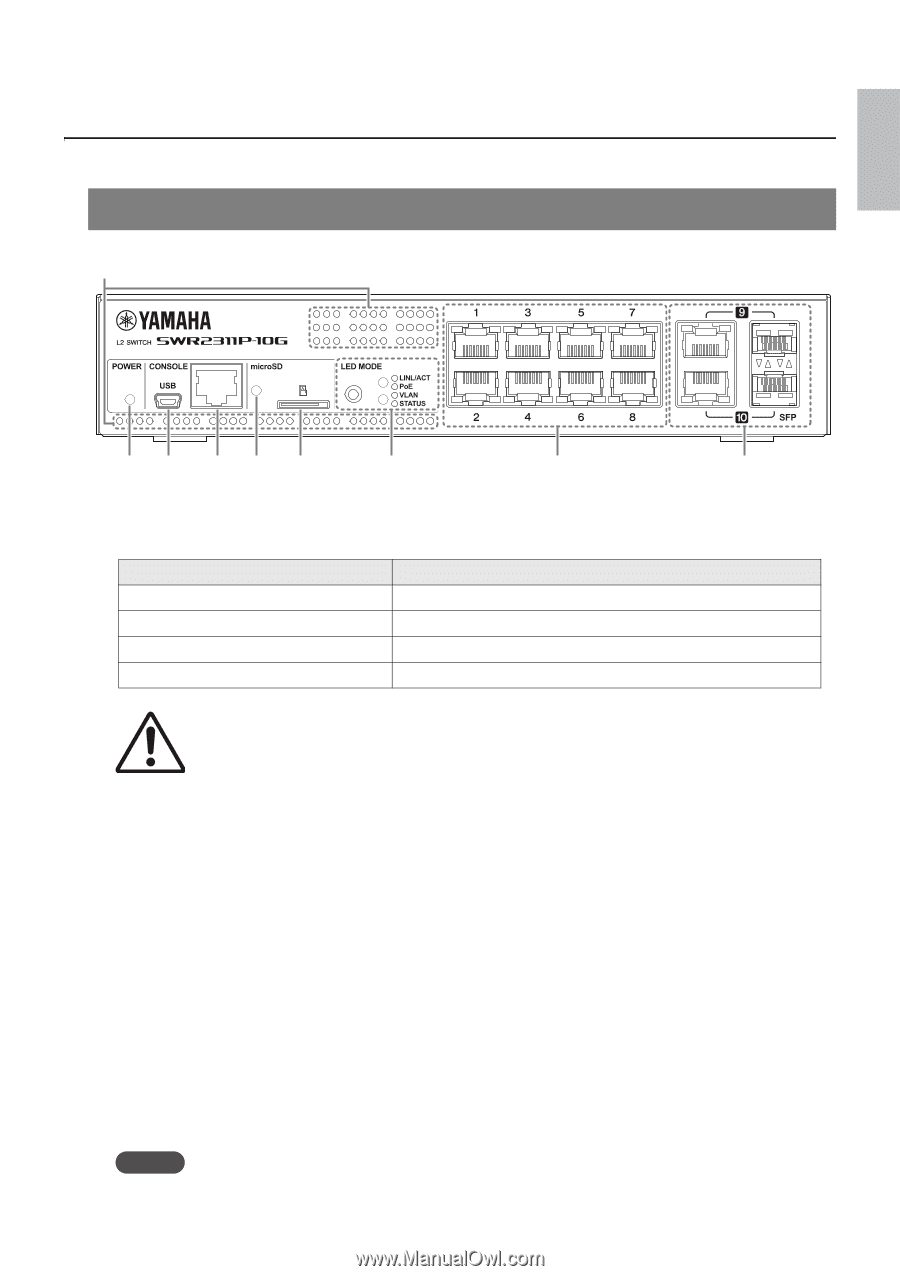
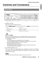
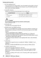
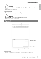
English Controls and Connectors Controls and Connectors Front Panel 9 12 34 5 6 7 8 1 POWER indicator Lights when power is provided to the unit. POWER indicator Unlit Flashing (green) Lit (green) Lit (orange) Status Power off Power on, starting up Power on, normal Power on, error occurred Caution When one of the following problems occurs, the POWER indicator is lit orange. Verify the status of the problem, and take the appropriate action. Refer to the Web GUI to determine which specific problem has occurred. • Fan stopped The fan that exhausts the heat dissipated by this unit has stopped. You must immediately stop using the unit, and contact a Yamaha service center listed at the end of this manual to have the unit repaired or inspected. • Abnormal temperature inside this unit. The temperature inside this unit is abnormal. Reconsider the environment in which this unit is installed, and correctly install this unit so that its internal temperature is appropriate. 2 mini-USB CONSOLE port This is a mini-USB port for making settings. Use a USB cable to connect it to the USB port of a computer. Use a USB cable equipped with a USB Type A connector and a mini-USB Type B (5-pin) connector. Notice Use a cable that supports data transfer. Charge-only cables cannot be used. SWR2311P-10G Owner's Manual 11
-
 1
1 -
2
-
3
-
4
-
5
-
 6
6 -
 7
7 -
 8
8 -
 9
9 -
 10
10 -
 11
11 -
 12
12 -
 13
13 -
 14
14 -
 15
15 -
 16
16 -
17
-
18
-
19
-
20
-
21
-
22
-
23
-
24
-
25
-
26
-
27
-
28
-
29
-
30
-
31
-
32
-
33
-
34
-
35
-
36
-
37
-
38
-
39
-
40
-
41
-
42
-
43
-
44
 |
 |