Yamaha SWR2311P-10G SWR2311P-10G Owners Manual - Page 16
Switching the display mode, Wall mount accessory attachment holes
 |
View all Yamaha SWR2311P-10G manuals
Add to My Manuals
Save this manual to your list of manuals |
Page 16 highlights
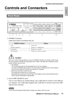
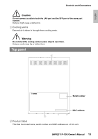
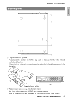
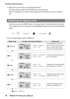
Controls and Connectors F Wall mount accessory attachment holes Use these holes to attach the WK-SWR wall mount accessory. Refer to "Installation on a wall or ceiling" (page 22) for information on how to install the unit. Switching the display mode Each time you press the MODE button, the display mode of the port indicators is switched. The lit status and color of the upper and lower MODE indicators shows the selected display mode. Unlit: Lit (green): Lit (orange): (when the initial display mode is LINK/ACT) Mode name 1 LINK/ACT Lit state of the mode indicators LED MODE LINL/ACT PoE VLAN STATUS Upper Lit (green) Lower Unlit Explanation The left indicator of the LAN port or SFP port shows the link status, and the right indicator shows the connection speed. 2 PoE LED MODE LINL/ACT PoE VLAN STATUS Upper Lit (orange) Indicates the power supply sta- Lower Unlit tus of the LAN port. 3 VLAN LED MODE LINL/ACT PoE VLAN STATUS Upper Unlit Lower Lit (green) Indicates the VLAN ID specified for the LAN port or SPF port. 4 STATUS LED MODE LINL/ACT PoE VLAN STATUS Upper Unlit Indicates the error status of the Lower Lit (orange) LAN port or SFP port. 5 OFF LED MODE 1 Back to LINK/ACT LINL/ACT PoE VLAN STATUS Upper Unlit Lower Unlit Turns off the indicators of the LAN ports and SFP ports. 16 SWR2311P-10G Owner's Manual
-
 1
1 -
2
-
3
-
4
-
5
-
6
-
7
-
8
-
9
-
10
-
 11
11 -
 12
12 -
 13
13 -
 14
14 -
 15
15 -
 16
16 -
 17
17 -
 18
18 -
 19
19 -
 20
20 -
 21
21 -
22
-
23
-
24
-
25
-
26
-
27
-
28
-
29
-
30
-
31
-
32
-
33
-
34
-
35
-
36
-
37
-
38
-
39
-
40
-
41
-
42
-
43
-
44
 |
 |
