Yamaha SWR2311P-10G SWR2311P-10G Owners Manual - Page 18
PoE mode, VLAN mode, STATUS mode
 |
View all Yamaha SWR2311P-10G manuals
Add to My Manuals
Save this manual to your list of manuals |
Page 18 highlights
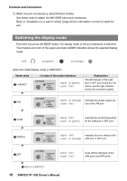
Controls and Connectors ■ PoE mode Indicates the power supply status. Left indicator Unlit Lit (green) Power supply status Not supplying power. Supplying power. The right indicator is unlit. ■ VLAN mode Indicates the VLAN membership status of the LAN port or SFP port. Left indicator Right indicator VLAN ID Unlit Lit (green) Lit (orange) Unlit Unlit Lit (green) Lit (orange) Lit (green)*1 Lit (orange) Unlit Unlit Unlit Lit (green) Lit (orange) Lit (orange) Lit (green) Lit (green)*1 Lit (orange) No ID Lowest-numbered VLAN ID The lit pattern is assigned in ascending order of the VLAN ID number. 7th and subsequent VLAN ID Membership in more than one VLAN *1 Indicators whose VLAN ID is number 7 or later will have the same lit status. NOTE The default VLAN (ID=1) is not shown as a member VLAN. Indicator assignment order 1 2 3 4 5 6 7 ■ STATUS mode Indicates the error status of the LAN port or SFP port. When the following errors are detected, the unit forcibly enters STATUS mode. • Loop detected • SFP optical input level abnormality detected • PoE supply stoppage or receiving device error detected 18 SWR2311P-10G Owner's Manual
-
 1
1 -
2
-
3
-
4
-
5
-
6
-
7
-
8
-
9
-
10
-
11
-
12
-
 13
13 -
 14
14 -
 15
15 -
 16
16 -
 17
17 -
 18
18 -
 19
19 -
 20
20 -
 21
21 -
 22
22 -
 23
23 -
24
-
25
-
26
-
27
-
28
-
29
-
30
-
31
-
32
-
33
-
34
-
35
-
36
-
37
-
38
-
39
-
40
-
41
-
42
-
43
-
44
 |
 |
