Yamaha SWR2311P-10G SWR2311P-10G Owners Manual - Page 12
RJ-45 CONSOLE port, microSD indicator, microSD slot, MODE button and MODE indicator, LAN ports
 |
View all Yamaha SWR2311P-10G manuals
Add to My Manuals
Save this manual to your list of manuals |
Page 12 highlights
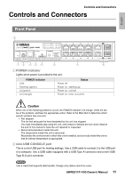
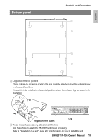
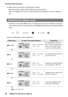
Controls and Connectors 3 RJ-45 CONSOLE port This is an RJ-45 port for making settings. Use an RJ-45/DB-9 console cable to connect it to the RS-232C connector (COM port) of the computer. Use an RJ-45/DB-9 serial cable that is wired as described in "Appendix." 4 microSD indicator Indicates the connected and operating status of the microSD card. microSD indicator Unlit Flashing (green) Lit (green) Status No microSD card is inserted in the slot. The microSD card is being accessed. A microSD card is inserted in the slot. Caution Do not remove the microSD card if this indicator is flashing green. Doing so will damage the data. 5 microSD slot A microSD card can be inserted in this slot. 6 MODE button and MODE indicator When you press the MODE button, the display mode of the port indicators is switched in the following sequence, allowing you to check the current status by the upper and lower MODE indicators. • When the initial display mode is LINK/ACT [LINK/ACT] [PoE] [VLAN] [STATUS] [OFF] back to [LINK/ACT]. • For details on the MODE button that switches modes and the MOD indicator, refer to "Switching the display mode" (page 16). • For details on the port indicators in each selected mode, refer to "Port indicators" (page 17). 7 LAN ports These ports can supply PoE and are compatible with 10BASE-T, 100BASE-TX, and 1000BASE-T. PoE supply is compliant with IEEE 802.3at, and can supply up to 30W to all ports. 8 LAN/SFP combo ports These can be used either as LAN ports or SFP ports. LAN ports are 1000BASE-T uplink ports. They do not have power supply capability. SFP ports are for installing a separately sold SFP module (SFP-SWRG-LX or SFPSWRG-SX). For details on installing an SFP module, refer to "Installing an SFP module" (page 28) in "Connections." 12 SWR2311P-10G Owner's Manual
-
 1
1 -
2
-
3
-
4
-
5
-
6
-
 7
7 -
 8
8 -
 9
9 -
 10
10 -
 11
11 -
 12
12 -
 13
13 -
 14
14 -
 15
15 -
 16
16 -
 17
17 -
18
-
19
-
20
-
21
-
22
-
23
-
24
-
25
-
26
-
27
-
28
-
29
-
30
-
31
-
32
-
33
-
34
-
35
-
36
-
37
-
38
-
39
-
40
-
41
-
42
-
43
-
44
 |
 |
