Yamaha SWR2311P-10G SWR2311P-10G Owners Manual - Page 14
Rear panel, Side panel, Power cord clamp attachment holes, Power supply inlet three-pin connector
 |
View all Yamaha SWR2311P-10G manuals
Add to My Manuals
Save this manual to your list of manuals |
Page 14 highlights
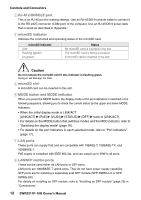
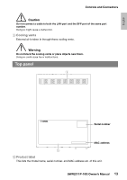
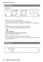
Controls and Connectors Rear panel Serial number A B C A Power cord clamp attachment holes The included power cord clamp (C-shaped) can be attached here. Refer to "Connecting the power cord" (page 30) for information on how to install the unit. B Fans These forcibly exhaust the heat that is generated inside the unit. When a problem is detected, the POWER indicator is lit orange. Caution Do not block the fan vents or place objects near them. Doing so could cause fire or malfunctions. C Power supply inlet (three-pin connector, C14 type) Insert the included power supply cord here. Connect it to an electrical outlet of the appropriate voltage for the unit. Side panel 9 14 SWR2311P-10G Owner's Manual
-
 1
1 -
2
-
3
-
4
-
5
-
6
-
7
-
8
-
 9
9 -
 10
10 -
 11
11 -
 12
12 -
 13
13 -
 14
14 -
 15
15 -
 16
16 -
 17
17 -
 18
18 -
 19
19 -
20
-
21
-
22
-
23
-
24
-
25
-
26
-
27
-
28
-
29
-
30
-
31
-
32
-
33
-
34
-
35
-
36
-
37
-
38
-
39
-
40
-
41
-
42
-
43
-
44
 |
 |

Controls and Connectors
14
SWR2311P-10G Owner’s Manual
A
Power cord clamp attachment holes
The included power cord clamp (C-shaped) can be attached here.
Refer to “Connecting the power cord” (page 30) for information on how to install the unit.
B
Fans
These forcibly exhaust the heat that is generated inside the unit.
When a problem is detected, the POWER indicator is lit orange.
Caution
Do not block the fan vents or place objects near them.
Doing so could cause fire or malfunctions.
C
Power supply inlet (three-pin connector, C14 type)
Insert the included power supply cord here. Connect it to an electrical outlet of the appro-
priate voltage for the unit.
Rear panel
Side panel
A
C
B
Serial number
9