Yamaha YSP-2700 Owners Manual - Page 9
Center unit rear, HDMI OUT ARC jack - firmware update
 |
View all Yamaha YSP-2700 manuals
Add to My Manuals
Save this manual to your list of manuals |
Page 9 highlights
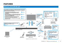
Center unit (rear) 123 4 5 6 7 INTELLIBEAM SYSTEM SUBWOOFER MIC CONNECTOR OUT R AUX1 L AUX2 TV NETWORK 8 9 OUT (ARC) HDMI IN 1 IN 2 0 IN 3 UPDATE ONLY INTELLIBEAM SYSTEM SUBWOOFER MIC CONNECTOR OUT R AUX1 L AUX2 TV NETWORK OUT (ARC) HDMI IN 1 IN 2 IN 3 UPDATE ONLY A B 1 INTELLIBEAM MIC jack For connecting the supplied IntelliBeam microphone (p. 33). 2 SYSTEM CONNECTOR jack For connecting to the supplied subwoofer using a wired connection (p. 29). 3 SUBWOOFER OUT jack For connecting to the supplied subwoofer using a wired connection (p. 29). 4 AUX1 input jacks For connecting to a playback device equipped with the analog audio output jacks (p. 26). 5 AUX2 input jack For connecting to a playback device equipped with a coaxial digital audio output jack (p. 25). 6 TV input jack For connecting to a TV equipped with an optical digital audio output jack (p. 24). 7 NETWORK jack For connecting to a network with a network cable (p. 27). 8 HDMI OUT (ARC) jack For connecting to an HDMI-compatible TV and outputting video/audio signals (p. 24). 9 HDMI IN 1-3 jacks For connecting an HDMI-compatible playback device such as a BD/DVD player, a satellite and cable TV tuner, and a game console (p. 25). 0 UPDATE ONLY jack Use to update this unit's firmware (p. 92). A Antenna Raise the antenna after the unit is installed (p. 23). B Power cable For connecting to an AC wall outlet (p. 28). FEATURES ➤ Controls and functions En 9
-
 1
1 -
2
-
3
-
 4
4 -
 5
5 -
 6
6 -
 7
7 -
 8
8 -
 9
9 -
 10
10 -
 11
11 -
 12
12 -
 13
13 -
 14
14 -
15
-
16
-
17
-
18
-
19
-
20
-
21
-
22
-
23
-
24
-
25
-
26
-
27
-
28
-
29
-
30
-
31
-
32
-
33
-
34
-
35
-
36
-
37
-
38
-
39
-
40
-
41
-
42
-
43
-
44
-
45
-
46
-
47
-
48
-
49
-
50
-
51
-
52
-
53
-
54
-
55
-
56
-
57
-
58
-
59
-
60
-
61
-
62
-
63
-
64
-
65
-
66
-
67
-
68
-
69
-
70
-
71
-
72
-
73
-
74
-
75
-
76
-
77
-
78
-
79
-
80
-
81
-
82
-
83
-
84
-
85
-
86
-
87
-
88
-
89
-
90
-
91
-
92
-
93
-
94
-
95
-
96
-
97
-
98
-
99
-
100
-
101
-
102
-
103
-
104
-
105
-
106
-
107
-
108
-
109
-
110
-
111
-
112
-
113
-
114
 |
 |
