Cisco 7206VXR Installation Guide - Page 85
Fast Ethernet MII Connection Equipment, Fast Ethernet Port Connection, MII Port
 |
UPC - 746320975061
View all Cisco 7206VXR manuals
Add to My Manuals
Save this manual to your list of manuals |
Page 85 highlights
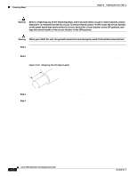
Chapter 3 Installing the Cisco 7206 Connecting I/O Controller Cables Fast Ethernet MII Connection Equipment The MII port on the I/O controller is a 40-pin, D-shell type connector that is configurable for 100 megabits per second (Mbps) full-duplex or half-duplex (half-duplex is the default). The MII port supports IEEE 802.3u interfaces compliant with the 100BASEX and 100BASET standards. The MII connection requires an external transceiver that permits connection to multimode fiber for 100BASEFX or 100BASET4 physical media (refer to Figure 3-15). Figure 3-15 Fast Ethernet Port Connection Optional Fast Ethernet port (MII receptacle and RJ-45 receptacle) ENABLED PCMCIA SLOT 1 EJECT SLOT 0 FE MII RJ-45 II M EN RJE4N5 RJL4I5NK R 1O PWOK RESET CPU FAST ETHERNET INPUT/OUTPUT CONTROLLER H6853 MII connector or RJ-45 connector To transceiver, repeater, or DTE To repeater or DTE Depending on the type of media you use between the MII connection and your switch or hub, the network side of your 100BASET transceiver should be appropriately equipped with ST-type connectors (for optical fiber), BNC connectors, and so forth. Figure 3-16 shows the pin orientation of the MII port on the I/O controller. The MII port uses two 56 screw-type locks, called jackscrews, to secure the cable or transceiver to the port. MII cables and transceivers have knurled thumbscrews that you fasten to the jackscrews on the MII connector and tighten with your fingers. Use the jackscrews to secure your MII cable to the MII port. Figure 3-16 MII Port Pin 1 H6538 Jackscrew Pin 21 Table 3-3 lists the pinouts and signals for the I/O controller MII port. OL-5102-02 Cisco 7206 Installation and Configuration Guide 3-17
-
 1
1 -
2
-
3
-
4
-
5
-
6
-
7
-
8
-
9
-
10
-
11
-
12
-
13
-
14
-
15
-
16
-
17
-
18
-
19
-
20
-
21
-
22
-
23
-
24
-
25
-
26
-
27
-
28
-
29
-
30
-
31
-
32
-
33
-
34
-
35
-
36
-
37
-
38
-
39
-
40
-
41
-
42
-
43
-
44
-
45
-
46
-
47
-
48
-
49
-
50
-
51
-
52
-
53
-
54
-
55
-
56
-
57
-
58
-
59
-
60
-
61
-
62
-
63
-
64
-
65
-
66
-
67
-
68
-
69
-
70
-
71
-
72
-
73
-
74
-
75
-
76
-
77
-
78
-
79
-
 80
80 -
 81
81 -
 82
82 -
 83
83 -
 84
84 -
 85
85 -
 86
86 -
 87
87 -
 88
88 -
 89
89 -
 90
90 -
91
-
92
-
93
-
94
-
95
-
96
-
97
-
98
-
99
-
100
-
101
-
102
-
103
-
104
-
105
-
106
-
107
-
108
-
109
-
110
-
111
-
112
-
113
-
114
-
115
-
116
-
117
-
118
-
119
-
120
-
121
-
122
-
123
-
124
-
125
-
126
-
127
-
128
-
129
-
130
-
131
-
132
-
133
-
134
-
135
-
136
-
137
-
138
-
139
-
140
-
141
-
142
-
143
-
144
-
145
-
146
-
147
-
148
-
149
-
150
 |
 |
