Cisco 7206VXR Installation Guide - Page 87
Straight-Through Cable Pinout, I/O Controller RJ-45 Connection to an End Station or DTE
 |
UPC - 746320975061
View all Cisco 7206VXR manuals
Add to My Manuals
Save this manual to your list of manuals |
Page 87 highlights
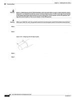
Chapter 3 Installing the Cisco 7206 Connecting I/O Controller Cables Table 3-4 RJ-45 Port Pinout Pin Description 1 Receive Data + (RxD+) 2 RxD- 3 Transmit Data + (TxD+) 6 TxD- Note With reference to the RJ-45 pinout in Table 3-4, proper common-mode line terminations should be used for the unused Category 5 UTP cable pairs 4/5 and 7/8. Common-mode line termination reduces electromagnetic interference (EMI). Depending on your I/O controller RJ-45 interface cabling requirements, use the pinouts shown in Figure 3-18 and Figure 3-19 for straight-through and crossover twisted-pair cable connections. Figure 3-18 Straight-Through Cable Pinout, I/O Controller RJ-45 Connection to an End Station or DTE Ethernet port 3 TxD+ 6 TxD- End station 3 RxD+ 6 RxD- H10416 1 RxD+ 2 RxD- 1 TxD+ 2 TxD- Figure 3-19 Crossover Cable Pinout, I/O Controller RJ-45 Connection to an End Station or DTE Ethernet port 3 TxD+ 6 TxD- Hub 3 TxD+ 6 TxD- H10417 1 RxD+ 2 RxD- 1 RxD+ 2 RxD- To identify the RJ-45 cable type, hold the two ends of the cable next to each other so you can see the colored wires inside the ends, as shown in Figure 3-20. OL-5102-02 Cisco 7206 Installation and Configuration Guide 3-19
-
 1
1 -
2
-
3
-
4
-
5
-
6
-
7
-
8
-
9
-
10
-
11
-
12
-
13
-
14
-
15
-
16
-
17
-
18
-
19
-
20
-
21
-
22
-
23
-
24
-
25
-
26
-
27
-
28
-
29
-
30
-
31
-
32
-
33
-
34
-
35
-
36
-
37
-
38
-
39
-
40
-
41
-
42
-
43
-
44
-
45
-
46
-
47
-
48
-
49
-
50
-
51
-
52
-
53
-
54
-
55
-
56
-
57
-
58
-
59
-
60
-
61
-
62
-
63
-
64
-
65
-
66
-
67
-
68
-
69
-
70
-
71
-
72
-
73
-
74
-
75
-
76
-
77
-
78
-
79
-
80
-
81
-
 82
82 -
 83
83 -
 84
84 -
 85
85 -
 86
86 -
 87
87 -
 88
88 -
 89
89 -
 90
90 -
 91
91 -
 92
92 -
93
-
94
-
95
-
96
-
97
-
98
-
99
-
100
-
101
-
102
-
103
-
104
-
105
-
106
-
107
-
108
-
109
-
110
-
111
-
112
-
113
-
114
-
115
-
116
-
117
-
118
-
119
-
120
-
121
-
122
-
123
-
124
-
125
-
126
-
127
-
128
-
129
-
130
-
131
-
132
-
133
-
134
-
135
-
136
-
137
-
138
-
139
-
140
-
141
-
142
-
143
-
144
-
145
-
146
-
147
-
148
-
149
-
150
 |
 |
