Cisco 7206VXR Installation Guide - Page 88
Connecting Power, Connecting AC-Input Power
 |
UPC - 746320975061
View all Cisco 7206VXR manuals
Add to My Manuals
Save this manual to your list of manuals |
Page 88 highlights
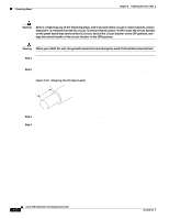
Connecting Power Figure 3-20 RJ-45 Cable Identification Chapter 3 Installing the Cisco 7206 H5663 Examine the sequence of colored wires to determine the type of RJ-45 cable, as follows: • Straight-through-The colored wires are in the same sequence at both ends of the cable. • Crossover-The first (far left) colored wire at one end of the cable is the third colored wire at the other end of the cable, and the second colored wire at one end of the cable is the sixth colored wire at the other end of the cable. Connecting Power Warning Before you install, operate, or service the system, read the Site Preparation and Safety Guide. This guide contains important safety information you should know before working with the system. This section provides the procedures for connecting AC-input and DC-input power to your Cisco 7206. Warning This unit might have more than one power cord. To reduce the risk of electric shock, disconnect the two power supply cords before servicing the unit. Note Detailed instructions for handling and replacing the Cisco 7206 power supplies are contained in the configuration notes 280-Watt AC-Input Power Supply Replacement Instructions and 280-Watt DC-Input Power Supply Replacement Instructions. These configuration notes are available on Cisco.com. Connecting AC-Input Power Connect a 280W AC-input power supply as follows: Step 1 At the rear of the router, check that the power switch is in the off (O) position. Step 2 Slide the cable-retention clip up, away from the AC receptacle, and plug in the power cable. 3-20 Cisco 7206 Installation and Configuration Guide OL-5102-02
-
 1
1 -
2
-
3
-
4
-
5
-
6
-
7
-
8
-
9
-
10
-
11
-
12
-
13
-
14
-
15
-
16
-
17
-
18
-
19
-
20
-
21
-
22
-
23
-
24
-
25
-
26
-
27
-
28
-
29
-
30
-
31
-
32
-
33
-
34
-
35
-
36
-
37
-
38
-
39
-
40
-
41
-
42
-
43
-
44
-
45
-
46
-
47
-
48
-
49
-
50
-
51
-
52
-
53
-
54
-
55
-
56
-
57
-
58
-
59
-
60
-
61
-
62
-
63
-
64
-
65
-
66
-
67
-
68
-
69
-
70
-
71
-
72
-
73
-
74
-
75
-
76
-
77
-
78
-
79
-
80
-
81
-
82
-
 83
83 -
 84
84 -
 85
85 -
 86
86 -
 87
87 -
 88
88 -
 89
89 -
 90
90 -
 91
91 -
 92
92 -
 93
93 -
94
-
95
-
96
-
97
-
98
-
99
-
100
-
101
-
102
-
103
-
104
-
105
-
106
-
107
-
108
-
109
-
110
-
111
-
112
-
113
-
114
-
115
-
116
-
117
-
118
-
119
-
120
-
121
-
122
-
123
-
124
-
125
-
126
-
127
-
128
-
129
-
130
-
131
-
132
-
133
-
134
-
135
-
136
-
137
-
138
-
139
-
140
-
141
-
142
-
143
-
144
-
145
-
146
-
147
-
148
-
149
-
150
 |
 |
