Compaq Presario 18XL Maintenance & Service Guide Presario 1800/1800T Serie - Page 106
Upper CPU Cover
 |
View all Compaq Presario 18XL manuals
Add to My Manuals
Save this manual to your list of manuals |
Page 106 highlights
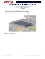
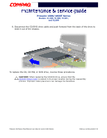
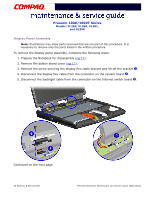
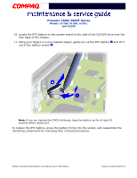
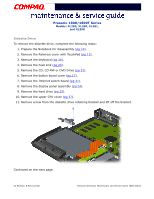
Presario 1800/1800T Series Models: XL280, XL380, XL381, and XL390 Upper CPU Cover To remove the upper CPU cover, complete the following steps: 1. Prepare the Notebook for disassembly (pg 10). 2. Remove the Palmrest cover with TouchPad (pg 13). 3. Remove the keyboard (pg 16). 4. Remove the heat sink (pg 23). 5. Remove the button board cover (pg 17). 6. Remove the Internet switch board (pg 21). 7. Remove the hard drive (pg 25). 8. Remove the display panel assembly (pg 34). 9. Remove the four screws (shown) located on the top of the upper CPU cover and lift the cover off the chassis. To replace the upper CPU cover, reverse these procedures. PRESARIO NOTEBOOK MAINTENANCE AND SERVICE GUIDE 1800 SERIES REMOVAL & REPLACEMENT 37
-
 1
1 -
2
-
3
-
4
-
5
-
6
-
7
-
8
-
9
-
10
-
11
-
12
-
13
-
14
-
15
-
16
-
17
-
18
-
19
-
20
-
21
-
22
-
23
-
24
-
25
-
26
-
27
-
28
-
29
-
30
-
31
-
32
-
33
-
34
-
35
-
36
-
37
-
38
-
39
-
40
-
41
-
42
-
43
-
44
-
45
-
46
-
47
-
48
-
49
-
50
-
51
-
52
-
53
-
54
-
55
-
56
-
57
-
58
-
59
-
60
-
61
-
62
-
63
-
64
-
65
-
66
-
67
-
68
-
69
-
70
-
71
-
72
-
73
-
74
-
75
-
76
-
77
-
78
-
79
-
80
-
81
-
82
-
83
-
84
-
85
-
86
-
87
-
88
-
89
-
90
-
91
-
92
-
93
-
94
-
95
-
96
-
97
-
98
-
99
-
100
-
 101
101 -
 102
102 -
 103
103 -
 104
104 -
 105
105 -
 106
106 -
 107
107 -
 108
108 -
 109
109 -
 110
110 -
 111
111 -
112
-
113
-
114
-
115
-
116
-
117
-
118
-
119
-
120
-
121
-
122
-
123
-
124
-
125
-
126
-
127
-
128
-
129
-
130
-
131
-
132
-
133
-
134
 |
 |

P
RESARIO
N
OTEBOOK
M
AINTENANCE
AND
S
ERVICE
G
UIDE
1800 S
ERIES
R
EMOVAL
& R
EPLACEMENT
37
Presario 1800/1800T Series
Models: XL280, XL380, XL381,
and XL390
Upper CPU Cover
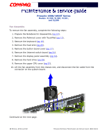
To remove the upper CPU cover, complete the following steps:
1.
Prepare the Notebook for disassembly (
pg 10
).
2.
Remove the Palmrest cover with TouchPad (
pg 13
).
3.
Remove the keyboard (
pg 16
).
4.
Remove the heat sink (
pg 23
).
5.
Remove the button board cover (
pg 17
).
6.
Remove the Internet switch board (
pg 21
).
7.
Remove the hard drive (
pg 25
).
8.
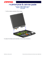
Remove the display panel assembly (
pg 34
).
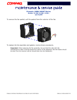
9.
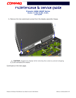
Remove the four screws (shown) located on the top of the upper CPU cover and lift
the cover off the chassis.
To replace the upper CPU cover, reverse these procedures.