Compaq Presario 18XL Maintenance & Service Guide Presario 1800/1800T Serie - Page 99
Fully align the processor pins with the socket holes on the connector.
 |
View all Compaq Presario 18XL manuals
Add to My Manuals
Save this manual to your list of manuals |
Page 99 highlights
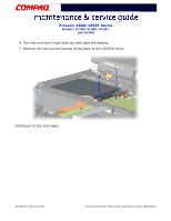
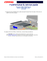
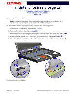
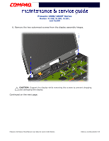
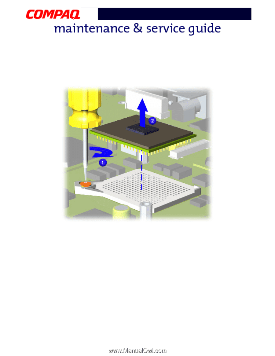
Presario 1800/1800T Series Models: XL280, XL380, XL381, and XL390 b. With standard screwdriver, turn screw counter-clockwise toward "0" 1 and lift processor from the chassis 2. To replace the processor, complete the following steps: 1. Fully align the processor pins with the socket holes on the connector. 2. Press down carefully on the processor directly over the connector to seat the it. 3. Once the processor is in place, reassemble the remaining subassemblies by reversing their removal procedures. 30 REMOVAL & REPLACEMENT PRESARIO NOTEBOOK MAINTENANCE AND SERVICE GUIDE 1800 SERIES
-
 1
1 -
2
-
3
-
4
-
5
-
6
-
7
-
8
-
9
-
10
-
11
-
12
-
13
-
14
-
15
-
16
-
17
-
18
-
19
-
20
-
21
-
22
-
23
-
24
-
25
-
26
-
27
-
28
-
29
-
30
-
31
-
32
-
33
-
34
-
35
-
36
-
37
-
38
-
39
-
40
-
41
-
42
-
43
-
44
-
45
-
46
-
47
-
48
-
49
-
50
-
51
-
52
-
53
-
54
-
55
-
56
-
57
-
58
-
59
-
60
-
61
-
62
-
63
-
64
-
65
-
66
-
67
-
68
-
69
-
70
-
71
-
72
-
73
-
74
-
75
-
76
-
77
-
78
-
79
-
80
-
81
-
82
-
83
-
84
-
85
-
86
-
87
-
88
-
89
-
90
-
91
-
92
-
93
-
 94
94 -
 95
95 -
 96
96 -
 97
97 -
 98
98 -
 99
99 -
 100
100 -
 101
101 -
 102
102 -
 103
103 -
 104
104 -
105
-
106
-
107
-
108
-
109
-
110
-
111
-
112
-
113
-
114
-
115
-
116
-
117
-
118
-
119
-
120
-
121
-
122
-
123
-
124
-
125
-
126
-
127
-
128
-
129
-
130
-
131
-
132
-
133
-
134
 |
 |
30 R
EMOVAL
& R
EPLACEMENT
P
RESARIO
N
OTEBOOK
M
AINTENANCE
AND
S
ERVICE
G
UIDE
1800 S
ERIES
Presario 1800/1800T Series
Models: XL280, XL380, XL381,
and XL390
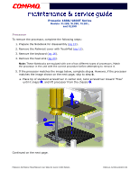
b. With standard screwdriver, turn screw counter-clockwise toward ±0²
1
and lift
processor from the chassis
2
.
To replace the processor, complete the following steps:
1.
Fully align the processor pins with the socket holes on the connector.
2.
Press down carefully on the processor directly over the connector to seat the it.
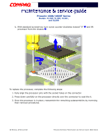
3.
Once the processor is in place, reassemble the remaining subassemblies by reversing
their removal procedures.