Dell Latitude E6400 Service Manual - Page 24
Replacing the I/O Card - keyboard
 |
View all Dell Latitude E6400 manuals
Add to My Manuals
Save this manual to your list of manuals |
Page 24 highlights
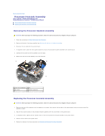
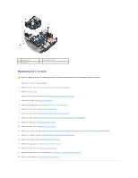
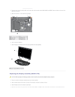
1 plastic plug 3 I/O card 2 M2 x 3-mm screw Replacing the I/O Card CAUTION: Before you begin the following procedure, follow the safety instructions that shipped with your computer. 1. Place the I/O card in the base assembly. 2. Replace the M2 x 3-mm screw to secure the I/O card to the base assembly. 3. Replace the plastic plug. 4. Replace the RJ-11 modem connector (see Replacing the RJ-11 Modem Connector). 5. Replace the modem (see Replacing the Modem). 6. Replace the system board (see Replacing the System Board Assembly). 7. Replace the card cage (see Replacing the Card Cage). 8. Replace the palm rest assembly (see Replacing the Palm Rest Assembly). 9. Replace the right speaker grill (see Replacing the Right Speaker Grill/Fingerprint Reader Assembly). 10. Replace the keyboard (see Replacing the Keyboard). 11. Replace the LED cover (see Replacing the LED Cover). 12. Replace the display assembly (see Replacing the Display Assembly (E6400 and M2400) or Replacing the Display Assembly (E6400 ATG)). 13. Replace the heatsink assembly (see Replacing the Processor Heatsink Assembly). 14. Replace the hinge covers (see Replacing the Hinge Covers). 15. Replace the modular drive (see Replacing the Modular Drive). 16. Replace the hard drive (see Replacing the Hard Drive). 17. Replace the bottom of the base assembly (see Replacing the Bottom of the Base Assembly). 18. Follow the procedures in After Working on Your Computer.
-
 1
1 -
2
-
3
-
4
-
5
-
6
-
7
-
8
-
9
-
10
-
11
-
12
-
13
-
14
-
15
-
16
-
17
-
18
-
 19
19 -
 20
20 -
 21
21 -
 22
22 -
 23
23 -
 24
24 -
 25
25 -
 26
26 -
 27
27 -
 28
28 -
 29
29 -
30
-
31
-
32
-
33
-
34
-
35
-
36
-
37
-
38
-
39
-
40
-
41
-
42
-
43
-
44
-
45
-
46
-
47
-
48
-
49
-
50
-
51
-
52
-
53
-
54
-
55
-
56
-
57
-
58
-
59
-
60
-
61
-
62
-
63
-
64
-
65
-
66
-
67
-
68
-
69
-
70
-
71
-
72
-
73
-
74
-
75
-
76
-
77
-
78
-
79
-
80
-
81
-
82
-
83
-
84
-
85
-
86
-
87
-
88
-
89
-
90
-
91
-
92
-
93
-
94
-
95
-
96
-
97
-
98
-
99
 |
 |
