Dell Latitude E6400 Service Manual - Page 8
Caution, Notice - keyboard replacement
 |
View all Dell Latitude E6400 manuals
Add to My Manuals
Save this manual to your list of manuals |
Page 8 highlights
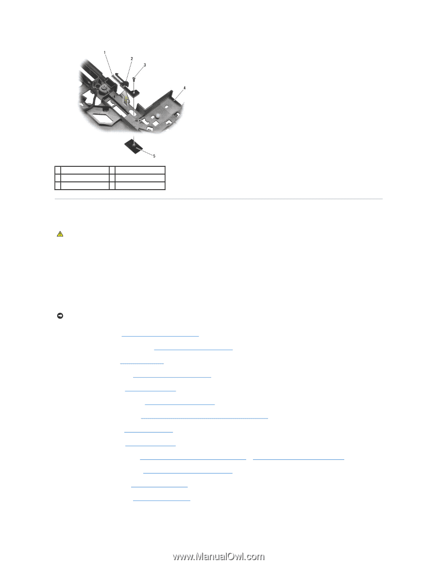
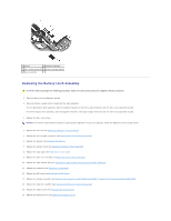
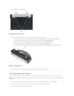
1 spring 2 alignment bracket 3 M2 x 3-mm screws (2) 4 battery release button 5 base assembly Replacing the Battery Latch Assembly CAUTION: Before you begin the following procedure, follow the safety instructions that shipped with your computer. 1. Place the spring on the alignment bracket. 2. Place the battery release button underneath the base assembly. For the right battery latch assembly, slide the alignment bracket to the left to align the button with the hole in the alignment bracket. For the left battery latch assembly, slide the alignment bracket to the right to align the button with the hole in the alignment bracket. 3. Replace the M2 x 3-mm screw. NOTICE: The battery release button is keyed to ensure proper alignment. If you feel resistance, check the alignment of the release button. 4. Replace the I/O card (see Replacing the Battery Latch Assembly). 5. Replace the RJ-11 modem connector (see Replacing the RJ-11 Modem Connector). 6. Replace the modem (see Replacing the Modem). 7. Replace the system board (see Replacing the System Board Assembly). 8. Replace the card cage (see Replacing the Card Cage). 9. Replace the palm rest assembly (see Replacing the Palm Rest Assembly). 10. Replace the right speaker grill (see Replacing the Right Speaker Grill/Fingerprint Reader Assembly). 11. Replace the keyboard (see Replacing the Keyboard). 12. Replace the LED cover (see Replacing the LED Cover). 13. Replace the display assembly (see Replacing the Display Assembly (E6400 and M2400) or Replacing the Display Assembly (E6400 ATG)). 14. Replace the heatsink assembly (see Replacing the Processor Heatsink Assembly). 15. Replace the hinge covers (see Replacing the Hinge Covers). 16. Replace the modular drive (see Replacing the Modular Drive).
-
 1
1 -
2
-
 3
3 -
 4
4 -
 5
5 -
 6
6 -
 7
7 -
 8
8 -
 9
9 -
 10
10 -
 11
11 -
 12
12 -
 13
13 -
14
-
15
-
16
-
17
-
18
-
19
-
20
-
21
-
22
-
23
-
24
-
25
-
26
-
27
-
28
-
29
-
30
-
31
-
32
-
33
-
34
-
35
-
36
-
37
-
38
-
39
-
40
-
41
-
42
-
43
-
44
-
45
-
46
-
47
-
48
-
49
-
50
-
51
-
52
-
53
-
54
-
55
-
56
-
57
-
58
-
59
-
60
-
61
-
62
-
63
-
64
-
65
-
66
-
67
-
68
-
69
-
70
-
71
-
72
-
73
-
74
-
75
-
76
-
77
-
78
-
79
-
80
-
81
-
82
-
83
-
84
-
85
-
86
-
87
-
88
-
89
-
90
-
91
-
92
-
93
-
94
-
95
-
96
-
97
-
98
-
99
 |
 |