Dell Latitude E6400 Service Manual - Page 3
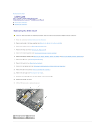
Replacing the 1394 Card - atg
 |
View all Dell Latitude E6400 manuals
Add to My Manuals
Save this manual to your list of manuals |
Page 3 highlights
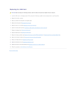
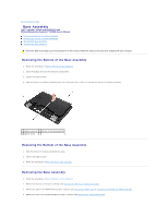
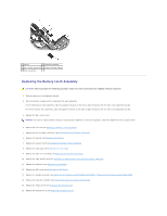
Replacing the 1394 Card CAUTION: Before you begin the following procedure, follow the safety instructions that shipped with your computer. 1. Insert the 1394 card at a 45-degree angle to fit the connector into the base assembly. Use the alignment pins to seat into position. 2. Replace the two M2 x 3 screws. 3. Route and connect the 1394 cable to the system board. 4. Replace the card cage (see Replacing the Card Cage). 5. Replace the palm rest assembly (Replacing the Palm Rest Assembly). 6. Replace the right speaker grill (see Replacing the Right Speaker Grill/Fingerprint Reader Assembly). 7. Replace the keyboard (see Replacing the Keyboard). 8. Replace the LED cover (see Replacing the LED Cover). 9. Replace the display assembly (see Replacing the Display Assembly (E6400 and M2400) or Replacing the Display Assembly (E6400 ATG)). 10. Replace the heatsink assembly (see Replacing the Processor Heatsink Assembly). 11. Replace the hinge covers (see Replacing the Hinge Covers). 12. Replace the modular drive (see Replacing the Modular Drive). 13. Replace the bottom of the base assembly (see Replacing the Bottom of the Base Assembly). 14. Follow the procedures in After Working on Your Computer. Back to Contents Page
-
 1
1 -
 2
2 -
 3
3 -
 4
4 -
 5
5 -
 6
6 -
 7
7 -
 8
8 -
 9
9 -
10
-
11
-
12
-
13
-
14
-
15
-
16
-
17
-
18
-
19
-
20
-
21
-
22
-
23
-
24
-
25
-
26
-
27
-
28
-
29
-
30
-
31
-
32
-
33
-
34
-
35
-
36
-
37
-
38
-
39
-
40
-
41
-
42
-
43
-
44
-
45
-
46
-
47
-
48
-
49
-
50
-
51
-
52
-
53
-
54
-
55
-
56
-
57
-
58
-
59
-
60
-
61
-
62
-
63
-
64
-
65
-
66
-
67
-
68
-
69
-
70
-
71
-
72
-
73
-
74
-
75
-
76
-
77
-
78
-
79
-
80
-
81
-
82
-
83
-
84
-
85
-
86
-
87
-
88
-
89
-
90
-
91
-
92
-
93
-
94
-
95
-
96
-
97
-
98
-
99
 |
 |
