Dell Latitude E6400 Service Manual - Page 31
Removing the Display Bezel E6400 ATG
 |
View all Dell Latitude E6400 manuals
Add to My Manuals
Save this manual to your list of manuals |
Page 31 highlights
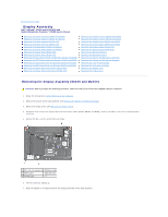
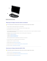
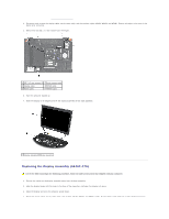
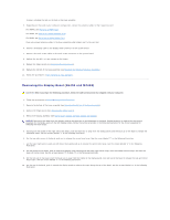
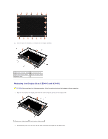
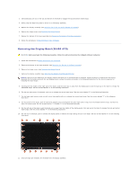
3. Simultaneously pull out on the top and bottom of the bezel to engage the top and bottom bezel snaps. 4. Gently snap the bezel into place to secure it to the display assembly. 5. Replace the display assembly (see Replacing the Display Assembly (E6400 and M2400)). 6. Replace the hinge covers (see Replacing the Hinge Covers). 7. Replace the bottom of the base assembly (see Replacing the Bottom of the Base Assembly). 8. Follow the procedures in After Working on Your Computer. Removing the Display Bezel (E6400 ATG) CAUTION: Before you begin the following procedure, follow the safety instructions that shipped with your computer. 1. Follow the instructions in Before Working on Your Computer. 2. Remove the bottom of the base assembly (see Removing the Bottom of the Base Assembly). 3. Remove the hinge covers (see Removing the Hinge Covers). 4. Remove the display assembly (see Removing the Display Assembly (E6400 ATG)). NOTICE: Removal of the bezel from the display requires extreme care to avoid damage to the bezel. Special attention is required for the corners, especially for the bezels used with the LED display panels. Follow the numbered arrows in the following illustration for the correct sequence for releasing the bezel snaps. 5. Starting with the middle of the right side of the bezel, push the bezel out or away from the display panel, and then pull up on the bezel to release the side bezel snaps. See the arrows labeled "1" in the following illustration. 6. For the top right corner of the bezel, push out to release the corner bezel snap. See the arrow labeled "2" in the following illustration. 7. For the lower right corner, push out with force, then gently pull up to release the corner bezel snap. See the arrows labeled "3" in the following illustration. 8. For the bottom of the bezel, push in toward the display panel starting with the lower right corner snap, then the middle bottom snaps, and then the lower left corner snap. See the arrows labeled "4" through "6" in the following illustration. 9. For the left side of the bezel, push the bezel out or away from the middle of the display panel, then pull up on the bezel to release the side and corner bezel snaps. See the arrows labeled "7" in the following illustration. 10. For the top of the bezel, push in toward the display panel to release the snaps along the top of the bezel. See the arrows labeled "8" in the following illustration. 11. Once all snaps are released, lift the bezel from the display assembly.
-
 1
1 -
2
-
3
-
4
-
5
-
6
-
7
-
8
-
9
-
10
-
11
-
12
-
13
-
14
-
15
-
16
-
17
-
18
-
19
-
20
-
21
-
22
-
23
-
24
-
25
-
 26
26 -
 27
27 -
 28
28 -
 29
29 -
 30
30 -
 31
31 -
 32
32 -
 33
33 -
 34
34 -
 35
35 -
 36
36 -
37
-
38
-
39
-
40
-
41
-
42
-
43
-
44
-
45
-
46
-
47
-
48
-
49
-
50
-
51
-
52
-
53
-
54
-
55
-
56
-
57
-
58
-
59
-
60
-
61
-
62
-
63
-
64
-
65
-
66
-
67
-
68
-
69
-
70
-
71
-
72
-
73
-
74
-
75
-
76
-
77
-
78
-
79
-
80
-
81
-
82
-
83
-
84
-
85
-
86
-
87
-
88
-
89
-
90
-
91
-
92
-
93
-
94
-
95
-
96
-
97
-
98
-
99
 |
 |
