Dell Latitude E6400 Service Manual - Page 72
Palm Rest Assembly - wireless switch
 |
View all Dell Latitude E6400 manuals
Add to My Manuals
Save this manual to your list of manuals |
Page 72 highlights
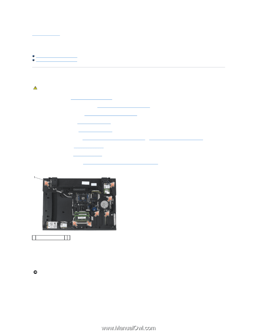
Back to Contents Page Palm Rest Assembly Dell™ Latitude™ E6400 and E6400 ATG and Mobile Workstation Precision™ M2400 Service Manual Removing the Palm Rest Assembly Replacing the Palm Rest Assembly Removing the Palm Rest Assembly CAUTION: Before you begin the following procedure, follow the safety instructions that shipped with your computer. 1. Follow the instructions in Before Working on Your Computer. 2. Remove the bottom of the base assembly (see Removing the Bottom of the Base Assembly). 3. Remove the heatsink assembly (see Removing the Processor Heatsink Assembly). 4. Remove the hinge covers (see Removing the Hinge Covers). 5. Remove the modular drive (see Removing the Modular Drive). 6. Remove the display assembly (see Removing the Display Assembly (E6400 and M2400) or Removing the Display Assembly (E6400 ATG)). 7. Remove the LED cover (see Removing the LED Cover). 8. Remove the keyboard (see Removing the Keyboard). 9. Remove the right speaker grill (see Removing the Right Speaker Grill/Fingerprint Reader Assembly). 10. Turn the computer over and remove seven M2.5 x 5-mm screws. 1 2.5 x 5-mm screws (7) 11. Turn the computer topside up and remove four M2.5 x 5-mm screws labeled "P". 12. Disconnect the wireless switch cable, the speaker cable, and the touch pad cable from the system board. 13. Lift the touch pad cable to reveal the contactless smart card cable underneath. Disconnect the contactless smart card cable from the system board. NOTICE: Do not use force to separate the palm rest from the computer. If you encounter resistance, gently flex or apply pressure to the palm rest, or move along the edge, working away from the area of resistance, until the palm rest is free. 14. Lift the left side of the palm rest, then push in on the right side to release the palm rest tabs from the base assembly. Pull the palm rest forward, then carefully lift it up from the computer.
-
 1
1 -
2
-
3
-
4
-
5
-
6
-
7
-
8
-
9
-
10
-
11
-
12
-
13
-
14
-
15
-
16
-
17
-
18
-
19
-
20
-
21
-
22
-
23
-
24
-
25
-
26
-
27
-
28
-
29
-
30
-
31
-
32
-
33
-
34
-
35
-
36
-
37
-
38
-
39
-
40
-
41
-
42
-
43
-
44
-
45
-
46
-
47
-
48
-
49
-
50
-
51
-
52
-
53
-
54
-
55
-
56
-
57
-
58
-
59
-
60
-
61
-
62
-
63
-
64
-
65
-
66
-
 67
67 -
 68
68 -
 69
69 -
 70
70 -
 71
71 -
 72
72 -
 73
73 -
 74
74 -
 75
75 -
 76
76 -
 77
77 -
78
-
79
-
80
-
81
-
82
-
83
-
84
-
85
-
86
-
87
-
88
-
89
-
90
-
91
-
92
-
93
-
94
-
95
-
96
-
97
-
98
-
99
 |
 |