Dell Latitude E6400 Service Manual - Page 34
Replacing the CCFL Display Panel and Brackets E6400 and M2400, Removing the LED Display Panel - led backlight not working
 |
View all Dell Latitude E6400 manuals
Add to My Manuals
Save this manual to your list of manuals |
Page 34 highlights
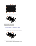
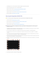
1 display panel 2 brackets (2) 3 M2 x 3-mm screws (8) Replacing the CCFL Display Panel and Brackets (E6400 and M2400) CAUTION: Before you begin the following procedure, follow the safety instructions that shipped with your computer. NOTE: The brackets are labeled "L" (left) and "R" (right). 1. Replace the four M2 x 3-mm screws on the right bracket and the four M2 x 3-mm screws on the left bracket. 2. Place the display panel upside down on your workspace in front of the display cover. 3. Connect the backlight cable to the inverter. 4. Connect the display cable to the connector on the back of the display panel. 5. Place the display panel in display cover. Use the alignment posts in the display cover to align each bracket. 6. Replace the four M2.5 x 5-mm screws that secure the display panel to the display cover. 7. Replace the display bezel (see Replacing the Display Bezel (E6400 and M2400)). 8. Replace the display assembly (see Replacing the Display Assembly (E6400 and M2400)). 9. Replace the hinge covers (see Replacing the Hinge Covers). 10. Replace the bottom of the base assembly (see Replacing the Bottom of the Base Assembly). 11. Follow the procedures in After Working on Your Computer. Removing the LED Display Panel and Brackets (E6400 and M2400) CAUTION: Before you begin the following procedure, follow the safety instructions that shipped with your computer. 1. Follow the instructions in Before Working on Your Computer. 2. Remove the bottom of the base assembly (see Removing the Bottom of the Base Assembly). 3. Remove the hinge covers (see Removing the Hinge Covers). 4. Remove the display assembly (see Removing the Display Assembly (E6400 and M2400)). 5. Remove the display bezel (see Removing the Display Bezel (E6400 and M2400)).
-
 1
1 -
2
-
3
-
4
-
5
-
6
-
7
-
8
-
9
-
10
-
11
-
12
-
13
-
14
-
15
-
16
-
17
-
18
-
19
-
20
-
21
-
22
-
23
-
24
-
25
-
26
-
27
-
28
-
 29
29 -
 30
30 -
 31
31 -
 32
32 -
 33
33 -
 34
34 -
 35
35 -
 36
36 -
 37
37 -
 38
38 -
 39
39 -
40
-
41
-
42
-
43
-
44
-
45
-
46
-
47
-
48
-
49
-
50
-
51
-
52
-
53
-
54
-
55
-
56
-
57
-
58
-
59
-
60
-
61
-
62
-
63
-
64
-
65
-
66
-
67
-
68
-
69
-
70
-
71
-
72
-
73
-
74
-
75
-
76
-
77
-
78
-
79
-
80
-
81
-
82
-
83
-
84
-
85
-
86
-
87
-
88
-
89
-
90
-
91
-
92
-
93
-
94
-
95
-
96
-
97
-
98
-
99
 |
 |
