Dell Latitude E6400 Service Manual - Page 35
Replacing the LED Display Panel and Brackets E6400 and M2400
 |
View all Dell Latitude E6400 manuals
Add to My Manuals
Save this manual to your list of manuals |
Page 35 highlights
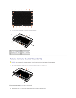
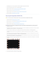
6. Remove the four M2.5 x 5-mm screws from the display panel. 1 M2.5 x 5-mm screws (4) 2 display panel 3 display cover 7. Lift the display panel out of the display cover and carefully lay the display panel flat on your workspace. Be careful to avoid damaging the display panel with the hinges and cables on the display cover. 8. Use the pull tab to disconnect the display cable. 1 display cable connector 2 display cable 3 underside of display panel 9. Remove two M2 x 3-mm screws from the right bracket and two M2 x 3-mm screws from the left bracket. 1 display panel 2 brackets (2) 3 M2 x 3-mm screws (4) Replacing the LED Display Panel and Brackets (E6400 and M2400)
-
 1
1 -
2
-
3
-
4
-
5
-
6
-
7
-
8
-
9
-
10
-
11
-
12
-
13
-
14
-
15
-
16
-
17
-
18
-
19
-
20
-
21
-
22
-
23
-
24
-
25
-
26
-
27
-
28
-
29
-
 30
30 -
 31
31 -
 32
32 -
 33
33 -
 34
34 -
 35
35 -
 36
36 -
 37
37 -
 38
38 -
 39
39 -
 40
40 -
41
-
42
-
43
-
44
-
45
-
46
-
47
-
48
-
49
-
50
-
51
-
52
-
53
-
54
-
55
-
56
-
57
-
58
-
59
-
60
-
61
-
62
-
63
-
64
-
65
-
66
-
67
-
68
-
69
-
70
-
71
-
72
-
73
-
74
-
75
-
76
-
77
-
78
-
79
-
80
-
81
-
82
-
83
-
84
-
85
-
86
-
87
-
88
-
89
-
90
-
91
-
92
-
93
-
94
-
95
-
96
-
97
-
98
-
99
 |
 |

6.
Remove the four M2.5 x 5-mm screws from the display panel.
7.
Lift the display panel out of the display cover and carefully lay the display panel flat on your workspace. Be careful to avoid damaging the display panel
with the hinges and cables on the display cover.
8.
Use the pull tab to disconnect the display cable.
9.
Remove two M2 x 3-mm screws from the right bracket and two
M2 x 3-mm screws from the left bracket.
Replacing the LED Display Panel and Brackets (E6400 and M2400)
1
M2.5 x 5-mm screws (4)
2
display panel
3
display cover
1
display cable connector
2
display cable
3
underside of display panel
1
display panel
2
brackets (2)
3
M2 x 3-mm screws (4)