Dell XPS 730 H2C Service Manual - Page 29
Replacing the Processor Fan Assembly, Replacing the Hard Drive Fan
 |
View all Dell XPS 730 H2C manuals
Add to My Manuals
Save this manual to your list of manuals |
Page 29 highlights
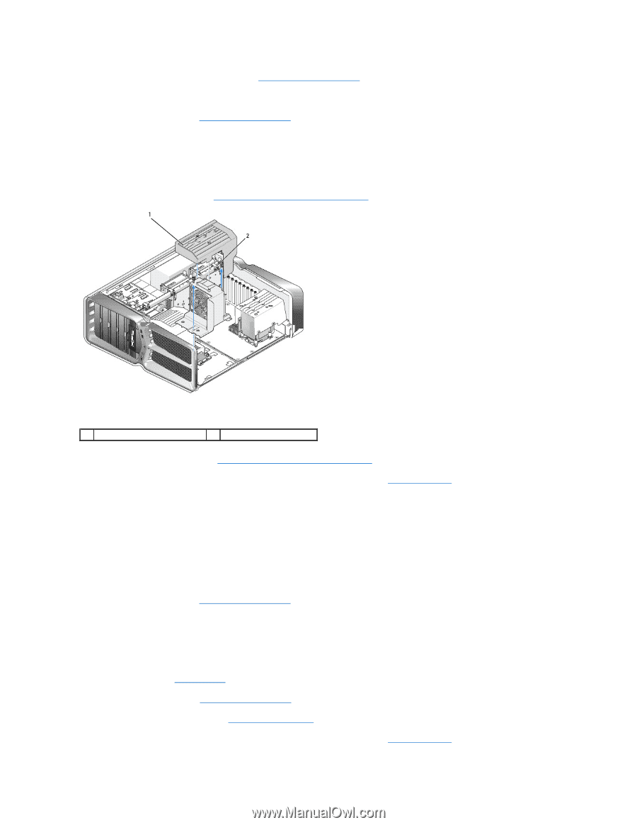
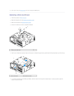
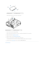
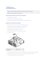
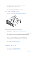
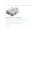
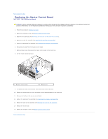
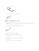
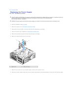
10. Replace any expansion cards that you removed (see Replacing a PCI/PCI Express Card). 11. Replace the PCI card fan shroud and captive screws on top of it. 12. Replace the computer cover (see Replacing the Computer Cover). 13. Connect your computer and devices to electrical outlets, and then turn them on. Replacing the Processor Fan Assembly 1. Remove the card slot fan shroud (see Removing the Card Slot and Processor Fan Shrouds). 1 processor fan shroud 2 captive screws (2) 2. Remove the processor fan shroud (see Removing the Card Slot and Processor Fan Shrouds) 3. Disconnect the fan cable from the FAN_CPU_FRONT connector on the Master Control Board (see Master Control Board). 4. Loosen the captive screws securing the processor fan shroud to the chassis, then rotate the shroud back. 5. To Install the processor fan assembly, align the hinge slots on the processor fan shroud with the hinge guides on the chassis. 6. Gently rotate the processor fan shroud towards the fan, and then tighten the two captive screws. 7. Connect the fan cable to the rear fan connector on the LED circuit board at the back of the chassis. 8. Replace the processor fan shroud on top o the processor fan assembly, and then tighten the two captive screws. 9. Replace the computer cover (see Replacing the Computer Cover). 10. Connect your computer and devices to electrical outlets, and turn them on. Replacing the Hard Drive Fan 1. Follow the procedures in Before You Begin. 2. Remove the computer cover (see Replacing the Computer Cover). 3. Remove all installed memory modules (see Replacing Memory Module(s)). 4. Disconnect the fan cable from the FAN_CPU_FRONT connector on the Master Control Board (see Master Control Board).
-
 1
1 -
2
-
3
-
4
-
5
-
6
-
7
-
8
-
9
-
10
-
11
-
12
-
13
-
14
-
15
-
16
-
17
-
18
-
19
-
20
-
21
-
22
-
23
-
 24
24 -
 25
25 -
 26
26 -
 27
27 -
 28
28 -
 29
29 -
 30
30 -
 31
31 -
 32
32 -
 33
33 -
 34
34 -
35
-
36
-
37
-
38
-
39
-
40
-
41
-
42
-
43
-
44
-
45
-
46
-
47
-
48
-
49
-
50
-
51
-
52
 |
 |