Fujitsu MHN2150AT Manual/User Guide - Page 118
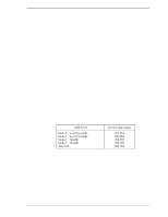
Data Transfer Mode, X'0B': Mode 3
 |
View all Fujitsu MHN2150AT manuals
Add to My Manuals
Save this manual to your list of manuals |
Page 118 highlights
Interface At command issuance (I/O registers setting contents) 1F7 (CM) 1 1 1 0 1 1 1 1 H 1F6H(DH) x x x DV xx 1F5H(CH) xx 1F4H(CL) xx 1F3H(SN) xx 1F2 (SC) xx or *1~3 H 1F1 (FR) [See Table 5.5] H At command completion (I/O registers contents to be read) 1F7H(ST) 1F6H(DH) 1F5 (CH) H 1F4H(CL) 1F3H(SN) 1F2H(SC) 1F1H(ER) Status information x x x DV xx xx xx xx xx Error information *1) Data Transfer Mode The host sets X'03' to the Features register. By issuing this command with setting a value to the Sector Count register, the transfer mode can be selected. Upper 5 bits of the Sector Count register defines the transfer type and lower 3 bits specifies the binary mode value. The IDD supports following values in the Sector Count register value. If other value than below is specified, an ABORTED COMMAND error is posted. PIO default transfer mode 00000 000 (X'00') PIO flow control transfer mode X 00001 000 (X'08': Mode 0) 00001 001 (X'09': Mode 1) 00001 010 (X'0A': Mode 2) 00001 011 (X'0B': Mode 3) 00001 100 (X'0C': Mode 4) 5-42 C141-E120-02EN
-
 1
1 -
2
-
3
-
4
-
5
-
6
-
7
-
8
-
9
-
10
-
11
-
12
-
13
-
14
-
15
-
16
-
17
-
18
-
19
-
20
-
21
-
22
-
23
-
24
-
25
-
26
-
27
-
28
-
29
-
30
-
31
-
32
-
33
-
34
-
35
-
36
-
37
-
38
-
39
-
40
-
41
-
42
-
43
-
44
-
45
-
46
-
47
-
48
-
49
-
50
-
51
-
52
-
53
-
54
-
55
-
56
-
57
-
58
-
59
-
60
-
61
-
62
-
63
-
64
-
65
-
66
-
67
-
68
-
69
-
70
-
71
-
72
-
73
-
74
-
75
-
76
-
77
-
78
-
79
-
80
-
81
-
82
-
83
-
84
-
85
-
86
-
87
-
88
-
89
-
90
-
91
-
92
-
93
-
94
-
95
-
96
-
97
-
98
-
99
-
100
-
101
-
102
-
103
-
104
-
105
-
106
-
107
-
108
-
109
-
110
-
111
-
112
-
 113
113 -
 114
114 -
 115
115 -
 116
116 -
 117
117 -
 118
118 -
 119
119 -
 120
120 -
 121
121 -
 122
122 -
 123
123 -
124
-
125
-
126
-
127
-
128
-
129
-
130
-
131
-
132
-
133
-
134
-
135
-
136
-
137
-
138
-
139
-
140
-
141
-
142
-
143
-
144
-
145
-
146
-
147
-
148
-
149
-
150
-
151
-
152
-
153
-
154
-
155
-
156
-
157
-
158
-
159
-
160
-
161
-
162
-
163
-
164
-
165
-
166
-
167
-
168
-
169
-
170
-
171
-
172
-
173
-
174
-
175
-
176
-
177
-
178
-
179
-
180
-
181
-
182
-
183
-
184
-
185
-
186
-
187
-
188
-
189
-
190
-
191
-
192
-
193
-
194
-
195
-
196
-
197
-
198
-
199
-
200
-
201
-
202
-
203
-
204
-
205
-
206
-
207
-
208
-
209
-
210
-
211
-
212
-
213
-
214
-
215
-
216
-
217
-
218
-
219
-
220
-
221
-
222
-
223
-
224
-
225
-
226
-
227
-
228
-
229
-
230
-
231
-
232
-
233
-
234
-
235
-
236
 |
 |
