Fujitsu MHN2150AT Manual/User Guide - Page 186
Series termination required for Ultra DMA, G X = X16 + X12 + X5 + 1.
 |
View all Fujitsu MHN2150AT manuals
Add to My Manuals
Save this manual to your list of manuals |
Page 186 highlights
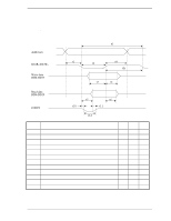
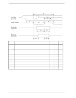
Interface i) The CRC generator polynomial is : G (X) = X16 + X12 + X5 + 1. Note: Since no bit clock is available, the recommended approach for calculating CRC is to use a word clock derived from the bus strobe. The combinational logic shall then be equivalent to shifting sixteen bits serially through the generator polynomial where DD0 is shifted in first and DD15 is shifted in last. 5.5.6 Series termination required for Ultra DMA Series termination resistors are required at both the host and the device for operation in any of the Ultra DMA Modes. The following table describes recommended values for series termination at the host and the device. Table 5.17 Recommended series termination for Ultra DMA Signal Host Termination Device Termination DIOR-:HDMARDY-:HSTROBE 22 ohm 82 ohm DIOW-:STOP 22 ohm 82 ohm CS0-, CS1- 33 ohm 82 ohm DA0, DA1, DA2 33 ohm 82 ohm DMACK- 22 ohm 82 ohm DD15 through DD0 33 ohm 33 ohm DMARQ 82 ohm 22 ohm INTRQ 82 ohm 22 ohm IORDY:DDMARDY-:DSTROBE 82 ohm 22 ohm RESET- 33 ohm 82 ohm Note: Only those signals requiring termination are listed in this table. If a signal is not listed, series termination is not required for operation in an Ultra DMA Mode. For signals also requiring a pull-up or pull-down resistor at the host see Figure 5.8. Vcc Figure 5.8 Ultra DMA termination with pull-up or pull-down 5-110 C141-E120-02EN
-
 1
1 -
2
-
3
-
4
-
5
-
6
-
7
-
8
-
9
-
10
-
11
-
12
-
13
-
14
-
15
-
16
-
17
-
18
-
19
-
20
-
21
-
22
-
23
-
24
-
25
-
26
-
27
-
28
-
29
-
30
-
31
-
32
-
33
-
34
-
35
-
36
-
37
-
38
-
39
-
40
-
41
-
42
-
43
-
44
-
45
-
46
-
47
-
48
-
49
-
50
-
51
-
52
-
53
-
54
-
55
-
56
-
57
-
58
-
59
-
60
-
61
-
62
-
63
-
64
-
65
-
66
-
67
-
68
-
69
-
70
-
71
-
72
-
73
-
74
-
75
-
76
-
77
-
78
-
79
-
80
-
81
-
82
-
83
-
84
-
85
-
86
-
87
-
88
-
89
-
90
-
91
-
92
-
93
-
94
-
95
-
96
-
97
-
98
-
99
-
100
-
101
-
102
-
103
-
104
-
105
-
106
-
107
-
108
-
109
-
110
-
111
-
112
-
113
-
114
-
115
-
116
-
117
-
118
-
119
-
120
-
121
-
122
-
123
-
124
-
125
-
126
-
127
-
128
-
129
-
130
-
131
-
132
-
133
-
134
-
135
-
136
-
137
-
138
-
139
-
140
-
141
-
142
-
143
-
144
-
145
-
146
-
147
-
148
-
149
-
150
-
151
-
152
-
153
-
154
-
155
-
156
-
157
-
158
-
159
-
160
-
161
-
162
-
163
-
164
-
165
-
166
-
167
-
168
-
169
-
170
-
171
-
172
-
173
-
174
-
175
-
176
-
177
-
178
-
179
-
180
-
 181
181 -
 182
182 -
 183
183 -
 184
184 -
 185
185 -
 186
186 -
 187
187 -
 188
188 -
 189
189 -
 190
190 -
 191
191 -
192
-
193
-
194
-
195
-
196
-
197
-
198
-
199
-
200
-
201
-
202
-
203
-
204
-
205
-
206
-
207
-
208
-
209
-
210
-
211
-
212
-
213
-
214
-
215
-
216
-
217
-
218
-
219
-
220
-
221
-
222
-
223
-
224
-
225
-
226
-
227
-
228
-
229
-
230
-
231
-
232
-
233
-
234
-
235
-
236
 |
 |
