Fujitsu MHN2150AT Manual/User Guide - Page 136
STANDBY X'96' or X'E2, Thus, when the command
 |
View all Fujitsu MHN2150AT manuals
Add to My Manuals
Save this manual to your list of manuals |
Page 136 highlights
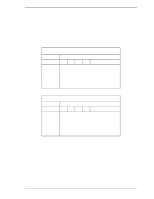
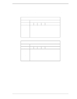
Interface (25) STANDBY (X'96' or X'E2') Upon receipt of this command, the device sets the BSY bit of the Status register and enters the standby mode. The device then clears the BSY bit and generates an interrupt. The device generates an interrupt even if the device has not fully entered the standby mode. If the device has already spun down, the spin-down sequence is not implemented. By using this command, the automatic power-down function is enabled and the timer starts the countdown when the device returns to idle mode. When the timer value reaches 0 (a specified time has padded), the device enters standby mode. Under the standby mode, the spindle motor is stopped. Thus, when the command involving a seek such as the READ SECTOR(s) command is received, the device processes the command after driving the spindle motor. At command issuance (I/O registers setting contents) 1F7 (CM) H 1F6H(DH) 1F5H(CH) 1F4H(CL) 1F3H(SN) 1F2 (SC) H 1F1 (FR) H X'96' or X'E2' xxx xx xx xx Period of timer xx DV xx At command completion (I/O registers contents to be read) 1F7H(ST) 1F6H(DH) 1F5 (CH) H 1F4H(CL) 1F3H(SN) 1F2H(SC) 1F1H(ER) Status information x x x DV xx xx xx xx xx Error information 5-60 C141-E120-02EN
-
 1
1 -
2
-
3
-
4
-
5
-
6
-
7
-
8
-
9
-
10
-
11
-
12
-
13
-
14
-
15
-
16
-
17
-
18
-
19
-
20
-
21
-
22
-
23
-
24
-
25
-
26
-
27
-
28
-
29
-
30
-
31
-
32
-
33
-
34
-
35
-
36
-
37
-
38
-
39
-
40
-
41
-
42
-
43
-
44
-
45
-
46
-
47
-
48
-
49
-
50
-
51
-
52
-
53
-
54
-
55
-
56
-
57
-
58
-
59
-
60
-
61
-
62
-
63
-
64
-
65
-
66
-
67
-
68
-
69
-
70
-
71
-
72
-
73
-
74
-
75
-
76
-
77
-
78
-
79
-
80
-
81
-
82
-
83
-
84
-
85
-
86
-
87
-
88
-
89
-
90
-
91
-
92
-
93
-
94
-
95
-
96
-
97
-
98
-
99
-
100
-
101
-
102
-
103
-
104
-
105
-
106
-
107
-
108
-
109
-
110
-
111
-
112
-
113
-
114
-
115
-
116
-
117
-
118
-
119
-
120
-
121
-
122
-
123
-
124
-
125
-
126
-
127
-
128
-
129
-
130
-
 131
131 -
 132
132 -
 133
133 -
 134
134 -
 135
135 -
 136
136 -
 137
137 -
 138
138 -
 139
139 -
 140
140 -
 141
141 -
142
-
143
-
144
-
145
-
146
-
147
-
148
-
149
-
150
-
151
-
152
-
153
-
154
-
155
-
156
-
157
-
158
-
159
-
160
-
161
-
162
-
163
-
164
-
165
-
166
-
167
-
168
-
169
-
170
-
171
-
172
-
173
-
174
-
175
-
176
-
177
-
178
-
179
-
180
-
181
-
182
-
183
-
184
-
185
-
186
-
187
-
188
-
189
-
190
-
191
-
192
-
193
-
194
-
195
-
196
-
197
-
198
-
199
-
200
-
201
-
202
-
203
-
204
-
205
-
206
-
207
-
208
-
209
-
210
-
211
-
212
-
213
-
214
-
215
-
216
-
217
-
218
-
219
-
220
-
221
-
222
-
223
-
224
-
225
-
226
-
227
-
228
-
229
-
230
-
231
-
232
-
233
-
234
-
235
-
236
 |
 |
