Fujitsu MHN2150AT Manual/User Guide - Page 82
Logical Interface
 |
View all Fujitsu MHN2150AT manuals
Add to My Manuals
Save this manual to your list of manuals |
Page 82 highlights
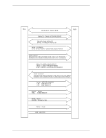
Interface [signal] DMARQ +5 VDC GND [I/O] O I - [Description] This signal is used for DMA transfer between the host system and the device. The device asserts this signal when the device completes the preparation of DMA data transfer to the host system (at reading) or from the host system (at writing). The direction of data transfer is controlled by the DIOR and DIOW signals. This signal hand shakes with the DMACK-signal. In other words, the device negates the DMARQ signal after the host system asserts the DMACK signal. When there is other data to be transferred, the device asserts the DMARQ signal again. When the DMA data transfer is performed, IOCS16-, CS0- and CS1- signals are not asserted. The DMA data transfer is a 16-bit data transfer. +5 VDC power supplying to the device. Grounded signal at each signal wire. Note: "I" indicates input signal from the host to the device. "O" indicates output signal from the device to the host. "I/O" indicates common output or bi-directional signal between the host and the device. 5.2 Logical Interface The device can operate for command execution in either address-specified mode; cylinder-head-sector (CHS) or Logical block address (LBA) mode. The IDENTIFY DEVICE information indicates whether the device supports the LBA mode. When the host system specifies the LBA mode by setting bit 6 in the Device/Head register to 1, HS3 to HS0 bits of the Device/Head register indicates the head No. under the LBA mode, and all bits of the Cylinder High, Cylinder Low, and Sector Number registers are LBA bits. The sector No. under the LBA mode proceeds in the ascending order with the start point of LBA0 (defined as follows). LBA0 = [Cylinder 0, Head 0, Sector 1] Even if the host system changes the assignment of the CHS mode by the INITIALIZE DEVICE PARAMETER command, the sector LBA address is not changed. LBA = [((Cylinder No.) × (Number of head) + (Head No.)) × (Number of sector/track)] + (Sector No.) − 1 5-6 C141-E120-02EN
-
 1
1 -
2
-
3
-
4
-
5
-
6
-
7
-
8
-
9
-
10
-
11
-
12
-
13
-
14
-
15
-
16
-
17
-
18
-
19
-
20
-
21
-
22
-
23
-
24
-
25
-
26
-
27
-
28
-
29
-
30
-
31
-
32
-
33
-
34
-
35
-
36
-
37
-
38
-
39
-
40
-
41
-
42
-
43
-
44
-
45
-
46
-
47
-
48
-
49
-
50
-
51
-
52
-
53
-
54
-
55
-
56
-
57
-
58
-
59
-
60
-
61
-
62
-
63
-
64
-
65
-
66
-
67
-
68
-
69
-
70
-
71
-
72
-
73
-
74
-
75
-
76
-
 77
77 -
 78
78 -
 79
79 -
 80
80 -
 81
81 -
 82
82 -
 83
83 -
 84
84 -
 85
85 -
 86
86 -
 87
87 -
88
-
89
-
90
-
91
-
92
-
93
-
94
-
95
-
96
-
97
-
98
-
99
-
100
-
101
-
102
-
103
-
104
-
105
-
106
-
107
-
108
-
109
-
110
-
111
-
112
-
113
-
114
-
115
-
116
-
117
-
118
-
119
-
120
-
121
-
122
-
123
-
124
-
125
-
126
-
127
-
128
-
129
-
130
-
131
-
132
-
133
-
134
-
135
-
136
-
137
-
138
-
139
-
140
-
141
-
142
-
143
-
144
-
145
-
146
-
147
-
148
-
149
-
150
-
151
-
152
-
153
-
154
-
155
-
156
-
157
-
158
-
159
-
160
-
161
-
162
-
163
-
164
-
165
-
166
-
167
-
168
-
169
-
170
-
171
-
172
-
173
-
174
-
175
-
176
-
177
-
178
-
179
-
180
-
181
-
182
-
183
-
184
-
185
-
186
-
187
-
188
-
189
-
190
-
191
-
192
-
193
-
194
-
195
-
196
-
197
-
198
-
199
-
200
-
201
-
202
-
203
-
204
-
205
-
206
-
207
-
208
-
209
-
210
-
211
-
212
-
213
-
214
-
215
-
216
-
217
-
218
-
219
-
220
-
221
-
222
-
223
-
224
-
225
-
226
-
227
-
228
-
229
-
230
-
231
-
232
-
233
-
234
-
235
-
236
 |
 |
