Fujitsu MHN2150AT Manual/User Guide - Page 83
I/O registers, Table 5.2, I/O registers
 |
View all Fujitsu MHN2150AT manuals
Add to My Manuals
Save this manual to your list of manuals |
Page 83 highlights
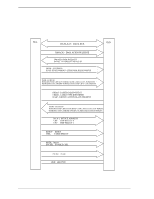
5.2 Logical Interface 5.2.1 I/O registers Communication between the host system and the device is done through inputoutput (I/O) registers of the device. These I/O registers can be selected by the coded signals, CS0-, CS1-, and DA0 to DA2 from the host system. Table 5.2. shows the coding address and the function of I/O registers. Table 5.2 I/O registers CS0- CS1- DA2 DA1 Command block registers L H L L L H L L L H L H L H L H L H H L L H H L L H H H L H H H L L X X Control block registers H L H H H L H H DA0 I/O registers Host I/O Read operation Write operation address L Data Data X'1F0' H Error Register Features X'1F1' L Sector Count Sector Count X'1F2' H Sector Number Sector Number X'1F3' L Cylinder Low Cylinder Low X'1F4' H Cylinder High Cylinder High X'1F5' L Device/Head Device/Head X'1F6' H Status Command X'1F7' X (Invalid) (Invalid) - L Alternate Status Device Control X'3F6' H - - X'3F7' Notes: 1. The Data register for read or write operation can be accessed by 16 bit data bus (DATA0 to DATA15). 2. The registers for read or write operation other than the Data registers can be accessed by 8 bit data bus (DATA0 to DATA7). 3. When reading the Drive Address register, bit 7 is high-impedance state. 4. H indicates signal level High and L indicates signal level Low. And the LBA mode is specified, the Device/Head, Cylinder High, Cylinder Low, and Sector Number registers indicate LBA bits 27 to 24, 23 to 16, 15 to 8, and 7 to 0. C141-E120-02EN 5-7
-
 1
1 -
2
-
3
-
4
-
5
-
6
-
7
-
8
-
9
-
10
-
11
-
12
-
13
-
14
-
15
-
16
-
17
-
18
-
19
-
20
-
21
-
22
-
23
-
24
-
25
-
26
-
27
-
28
-
29
-
30
-
31
-
32
-
33
-
34
-
35
-
36
-
37
-
38
-
39
-
40
-
41
-
42
-
43
-
44
-
45
-
46
-
47
-
48
-
49
-
50
-
51
-
52
-
53
-
54
-
55
-
56
-
57
-
58
-
59
-
60
-
61
-
62
-
63
-
64
-
65
-
66
-
67
-
68
-
69
-
70
-
71
-
72
-
73
-
74
-
75
-
76
-
77
-
 78
78 -
 79
79 -
 80
80 -
 81
81 -
 82
82 -
 83
83 -
 84
84 -
 85
85 -
 86
86 -
 87
87 -
 88
88 -
89
-
90
-
91
-
92
-
93
-
94
-
95
-
96
-
97
-
98
-
99
-
100
-
101
-
102
-
103
-
104
-
105
-
106
-
107
-
108
-
109
-
110
-
111
-
112
-
113
-
114
-
115
-
116
-
117
-
118
-
119
-
120
-
121
-
122
-
123
-
124
-
125
-
126
-
127
-
128
-
129
-
130
-
131
-
132
-
133
-
134
-
135
-
136
-
137
-
138
-
139
-
140
-
141
-
142
-
143
-
144
-
145
-
146
-
147
-
148
-
149
-
150
-
151
-
152
-
153
-
154
-
155
-
156
-
157
-
158
-
159
-
160
-
161
-
162
-
163
-
164
-
165
-
166
-
167
-
168
-
169
-
170
-
171
-
172
-
173
-
174
-
175
-
176
-
177
-
178
-
179
-
180
-
181
-
182
-
183
-
184
-
185
-
186
-
187
-
188
-
189
-
190
-
191
-
192
-
193
-
194
-
195
-
196
-
197
-
198
-
199
-
200
-
201
-
202
-
203
-
204
-
205
-
206
-
207
-
208
-
209
-
210
-
211
-
212
-
213
-
214
-
215
-
216
-
217
-
218
-
219
-
220
-
221
-
222
-
223
-
224
-
225
-
226
-
227
-
228
-
229
-
230
-
231
-
232
-
233
-
234
-
235
-
236
 |
 |
