Fujitsu MHN2150AT Manual/User Guide - Page 94
Fujitsu MHN2150AT - Mobile 15 GB Hard Drive Manual
 |
View all Fujitsu MHN2150AT manuals
Add to My Manuals
Save this manual to your list of manuals |
Page 94 highlights
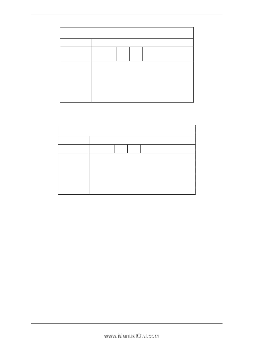
Interface At command issuance (I/O registers setting contents) 1F7 (CM) H 1F6H(DH) 1F5 (CH) H 1F4 (CL) H 1F3H(SN) 1F2H(SC) 1F1H(FR) 0 0 1 0 0 0 0R x L x DV Start head No. / LBA [MSB] Start cylinder No. [MSB] / LBA Start cylinder No. [LSB] / LBA Start sector No. / LBA [LSB] Transfer sector count xx (R: Retry) At command completion (I/O registers contents to be read) 1F7 (ST) H 1F6H(DH) 1F5H(CH) 1F4H(CL) 1F3H(SN) 1F2H(SC) 1F1 (ER) H Status information x L x DV End head No. / LBA [MSB] End cylinder No. [MSB] / LBA End cylinder No. [LSB] / LBA End sector No. / LBA [LSB] 00 (*1) Error information *1 If the command is terminated due to an error, the remaining number of sectors of which data was not transferred is set in this register. (2) READ MULTIPLE (X'C4') The READ MULTIPLE Command performs the same as the READ SECTOR(S) Command except that when the device is ready to transfer data for a block of sectors, and enters the interrupt pending state only before the data transfer for the first sector of the block sectors. In the READ MULTIPLE command operation, the DRQ bit of the Status register is set only at the start of the data block, and is not set on each sector. The number of sectors per block is defined by a successful SET MULTIPLE MODE Command. The SET MULTIPLE MODE command should be executed prior to the READ MULTIPLE command. If the number of requested sectors is not divided evenly (having the same number of sectors [block count]), as many full blocks as possible are transferred, then a 5-18 C141-E120-02EN
-
 1
1 -
2
-
3
-
4
-
5
-
6
-
7
-
8
-
9
-
10
-
11
-
12
-
13
-
14
-
15
-
16
-
17
-
18
-
19
-
20
-
21
-
22
-
23
-
24
-
25
-
26
-
27
-
28
-
29
-
30
-
31
-
32
-
33
-
34
-
35
-
36
-
37
-
38
-
39
-
40
-
41
-
42
-
43
-
44
-
45
-
46
-
47
-
48
-
49
-
50
-
51
-
52
-
53
-
54
-
55
-
56
-
57
-
58
-
59
-
60
-
61
-
62
-
63
-
64
-
65
-
66
-
67
-
68
-
69
-
70
-
71
-
72
-
73
-
74
-
75
-
76
-
77
-
78
-
79
-
80
-
81
-
82
-
83
-
84
-
85
-
86
-
87
-
88
-
 89
89 -
 90
90 -
 91
91 -
 92
92 -
 93
93 -
 94
94 -
 95
95 -
 96
96 -
 97
97 -
 98
98 -
 99
99 -
100
-
101
-
102
-
103
-
104
-
105
-
106
-
107
-
108
-
109
-
110
-
111
-
112
-
113
-
114
-
115
-
116
-
117
-
118
-
119
-
120
-
121
-
122
-
123
-
124
-
125
-
126
-
127
-
128
-
129
-
130
-
131
-
132
-
133
-
134
-
135
-
136
-
137
-
138
-
139
-
140
-
141
-
142
-
143
-
144
-
145
-
146
-
147
-
148
-
149
-
150
-
151
-
152
-
153
-
154
-
155
-
156
-
157
-
158
-
159
-
160
-
161
-
162
-
163
-
164
-
165
-
166
-
167
-
168
-
169
-
170
-
171
-
172
-
173
-
174
-
175
-
176
-
177
-
178
-
179
-
180
-
181
-
182
-
183
-
184
-
185
-
186
-
187
-
188
-
189
-
190
-
191
-
192
-
193
-
194
-
195
-
196
-
197
-
198
-
199
-
200
-
201
-
202
-
203
-
204
-
205
-
206
-
207
-
208
-
209
-
210
-
211
-
212
-
213
-
214
-
215
-
216
-
217
-
218
-
219
-
220
-
221
-
222
-
223
-
224
-
225
-
226
-
227
-
228
-
229
-
230
-
231
-
232
-
233
-
234
-
235
-
236
 |
 |