Garmin GTR 200 GTR 200 Installation Manual
Garmin GTR 200 Manual
 |
View all Garmin GTR 200 manuals
Add to My Manuals
Save this manual to your list of manuals |
Garmin GTR 200 manual content summary:
- Garmin GTR 200 | GTR 200 Installation Manual - Page 1
GTR 200 COM Transceiver Installation Manual 190-01553-00 July, 2013 Revision A - Garmin GTR 200 | GTR 200 Installation Manual - Page 2
commercial distribution of this manual or any revision hereto is strictly prohibited. Garmin International, Inc. 1200 E. 151st Street Olathe, KS 66062 USA Telephone: 913.397.8200 Aviation Panel-Mount Technical Support Line (Toll Free) 1.888.606.5482 www.garmin.com Garmin (Europe) Ltd. Liberty House - Garmin GTR 200 | GTR 200 Installation Manual - Page 3
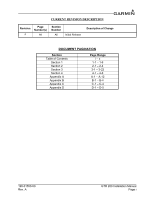
of Change DOCUMENT PAGINATION Section Table of Contents Section 1 Section 2 Section 3 Section 4 Appendix A Appendix B Appendix C Appendix D Page Range i - x 1-1 - 1-6 2-1 - 2-4 3-1 - 3-22 4-1 - 4-6 A-1 - A-12 B-1 - B-4 C-1 - C-4 D-1 - D-5 190-01553-00 Rev. A GTR 200 Installation Manual Page i - Garmin GTR 200 | GTR 200 Installation Manual - Page 4
www.garmin.com/prop65. CAUTION The front bezel, keypad, and display can be cleaned with a microfiber cloth or with a soft cotton cloth dampened with clean water. DO NOT use any chemical cleaning agents. Care should be taken to avoid scratching the surface of the display. GTR 200 Installation Manual - Garmin GTR 200 | GTR 200 Installation Manual - Page 5
. 1200 East 151st Street Olathe, Kansas 66062, U.S.A. Phone:913/397.8200 FAX:913/397.0836 Garmin (Europe) Ltd. Liberty House, Bulls Copse Road Hounsdown Business Park Romsey, SO40 9RB, U.K. Phone:44/ (0) 870.8501241 FAX:44/ (0) 870.850125 190-01553-00 Rev. A GTR 200 Installation Manual Page iii - Garmin GTR 200 | GTR 200 Installation Manual - Page 6
This page intentionally left blank GTR 200 Installation Manual Page iv 190-01553-00 Rev. A - Garmin GTR 200 | GTR 200 Installation Manual - Page 7
3-1 3.1 Unpacking the unit...3-1 3.2 Wiring Harness Installation 3-1 3.3 Backshell Assembly...3-2 3.4 Mounting Requirements 3-2 3.5 Antenna Installation and Connections 3-3 3.6 Post Installation Configuration and Checkout Procedures 3-4 3.7 Unit Software ...3-20 3.8 Continued Airworthiness 3-22 - Garmin GTR 200 | GTR 200 Installation Manual - Page 8
Connector Installation Instructions A-1 A.1 Shield Block Installation Wires A-10 Appendix B Serial Interface Specifications B-1 B.1 RS-232 Inputs...B-1 B.2 RS-232 Outputs ...B-4 Appendix C Outline and Installation Drawings C-1 Appendix D Interconnect Examples D-1 GTR 200 Installation Manual - Garmin GTR 200 | GTR 200 Installation Manual - Page 9
OF FIGURES FIGURE PAGE Section 1 General Description 1-1 Section 2 Installation Overview 2-1 Section 3 Installation Procedures 3-1 Figure 3-1 GTR 200 Front Panel 3-4 Figure 3-2 Configuration Mode Home Page 3-5 Figure 3-3 COM Setup Page 3-7 Figure 3-4 ICS Sidetone Selection 3-8 Figure - Garmin GTR 200 | GTR 200 Installation Manual - Page 10
/Intercom/GDU 37X Interconnect Example......... D-2 Figure D-3 GTR 200- Power & Ground/GMA 240/GNS 430/aera 79X Interconnect Example ...D-3 Figure D-4 GTR 200- Mono Audio/Remote Mount Jack Interconnect Example D-4 Figure D-5 GTR 200- J2001 Connector Layout D-5 GTR 200 Installation Manual Page - Garmin GTR 200 | GTR 200 Installation Manual - Page 11
Cable Preparations for Garmin Connectors A-3 Table A-3 Shielded Cable Preparations - (Quick Term A-9 Appendix B Serial Interface Specifications B-1 Appendix C Outline and Installation Drawings C-1 Appendix D Interconnect Examples D-1 190-01553-00 Rev. A GTR 200 Installation Manual Page ix - Garmin GTR 200 | GTR 200 Installation Manual - Page 12
This page intentionally left blank GTR 200 Installation Manual Page x 190-01553-00 Rev. A - Garmin GTR 200 | GTR 200 Installation Manual - Page 13
based cell phones that are on, even in a monitoring state, can disrupt GPS/SBAS performance. NOTE All screen shots used in this document are current at software file names, versions, and part numbers, is subject to change and may not be up to date. 190-01553-00 Rev. A GTR 200 Installation Manual - Garmin GTR 200 | GTR 200 Installation Manual - Page 14
) Rack Width Depth Behind Panel with Connectors (Measured from face of aircraft panel to rear of connector backshells) GTR 200 Weight (Unit Only) GTR 200 (Installed with rack and connectors) draw is with the display backlight set to 100% GTR 200 Installation Manual Page 1-2 190-01553-00 Rev. A - Garmin GTR 200 | GTR 200 Installation Manual - Page 15
Width: 2.95" (74.98mm) Height: 0.486" (12.36mm) 200 x 33 pixels Left: 45 Right: 45° Up: 10 Down: 30 1.3.4 COM Specifications The GTR 200 transmitter meets the requirements of RTCA DO-186B section 2.3 for a class at 350 to 2500 Hz 190-01553-00 Rev. A GTR 200 Installation Manual Page 1-3 - Garmin GTR 200 | GTR 200 Installation Manual - Page 16
band information may be required for licensing and are detailed in Section 1.3.4. 1.3.6 Aircraft Radio An aircraft radio station license is not required when operating in U.S. airspace, but may be required when operating internationally. GTR 200 Installation Manual Page 1-4 190-01553-00 Rev. A - Garmin GTR 200 | GTR 200 Installation Manual - Page 17
Model GTR 200 FCC installing the GTR 200. Before installing the GTR 200, the installer should read all referenced materials along with the manual. Table 1-8 Reference Documents Part Number 190-01553-01 Document GTR 200 Pilot's Guide 190-01553-00 Rev. A GTR 200 Installation Manual - Garmin GTR 200 | GTR 200 Installation Manual - Page 18
This page intentionally left blank GTR 200 Installation Manual Page 1-6 190-01553-00 Rev. A - Garmin GTR 200 | GTR 200 Installation Manual - Page 19
1 37 Pin D-Sub Crimp Socket Connector 330-00625-37 1 Crimp Socket Contact, Size 20, 20-24 AWG 336-00022-02 37 190-01553-00 Rev. A GTR 200 Installation Manual Page 2-1 - Garmin GTR 200 | GTR 200 Installation Manual - Page 20
ADF sense antennas. The COM antenna should also be mounted as far as practical from the ELT antenna. Some ELTs have exhibited re-radiation problems that cause interference with other radios, including GPS. This can happen when the COM (GTR 200 or any other COM) is transmitting on certain frequencies - Garmin GTR 200 | GTR 200 Installation Manual - Page 21
all GPS antennas. If a COM is found to be radiating, the following can be done: • Replace or clean VHF COM rack connector to ensure good coax ground. • Place a grounding brace between the GTR 200 and ground. • Shield the GTR 200 wiring harness. 190-01553-00 Rev. A GTR 200 Installation Manual Page - Garmin GTR 200 | GTR 200 Installation Manual - Page 22
investment. 2.9 Compass Safe Distance After reconfiguring the avionics in the cockpit panel, if the unit is mounted less than 12 inches from the compass, recalibrate the compass and make the necessary changes for noting correction data. GTR 200 Installation Manual Page 2-4 190-01553-00 Rev. A - Garmin GTR 200 | GTR 200 Installation Manual - Page 23
to accommodate sufficient packing material to prevent movement. 3.2 Wiring Harness Installation Allow adequate space for installation of cables and connectors. The installer shall supply and fabricate all cables. All electrical connections to the GTR 200 are made through one 37-pin D-sub standard - Garmin GTR 200 | GTR 200 Installation Manual - Page 24
instructions. 3.4 Mounting Requirements 3.4.1 Rack Installation Use the dimensions shown in Appendix C to prepare the mounting holes for the unit. You may also use the GTR 200 unit mounting the aircraft panel. NOTE If the front lip of the mounting rack is behind the surface of the aircraft panel, the - Garmin GTR 200 | GTR 200 Installation Manual - Page 25
GTR 200 requires a standard 50 vertically polarized antenna. Follow the antenna manufacturer's installation instructions for mounting the antenna. The antenna should be mounted heat dissipated by the radio when the radio is transmitting. 190-01553-00 Rev. A GTR 200 Installation Manual Page 3-3 - Garmin GTR 200 | GTR 200 Installation Manual - Page 26
functioning correctly as well as instructions for configuring the GTR 200 to the specific installation. Follow the instructions in Section 3.6.2 through Section 3.6.7.1 in order to complete all post installation configuration and checkout procedures. 3.6.2 Mounting, Wiring, and Power Checks Verify - Garmin GTR 200 | GTR 200 Installation Manual - Page 27
Section 3.6.4.3 • SOFTKEY SETUP - See Section 3.6.4.4 • DISCRETE SETUP - See Section 3.6.4.5 • LIGHTING SETUP - See Section 3.6.4.6 • HEADSET TESTS - See Section 3.6.5.1 • COM TESTS - See Section 3.6.5.2 • AUDIO TESTS - See Section 3.6.5.3 190-01553-00 Rev. A GTR 200 Installation Manual Page 3-5 - Garmin GTR 200 | GTR 200 Installation Manual - Page 28
Note SIDETONE 5 COM SETUP MIC GAIN 5 RF SQLCH 0 INTERCOM ENABLED YES RECEIVER OUT GAIN 100% AUX 1 SQUELCH 30% AUDIO SETUP AUX 1 VOLUME 50% AUX 2 SQUELCH 30% AUX 2 VOLUME 50% PILOT ON RIGHT SIDE NO SOFTKEY SETUP KEY 1 KEY 2 USER LIST TUNE EMERGENCY DISC 1 PILOT ICS KEY - Garmin GTR 200 | GTR 200 Installation Manual - Page 29
to another function. Figure 3-3 COM Setup Page Table 3-4 COM Setup Page Selections Selection Description control panel. The Intercom Enable/Disable setting on the (Figure 3-4). Intercom volume is adjustable in normal mode (see Pilots Guide). Sidetone audio GTR 200 Installation Manual Page 3-7 - Garmin GTR 200 | GTR 200 Installation Manual - Page 30
SQLCH Table 3-4 COM Setup Page Selections Increasing this setting allows squelch to be broken with higher signal levels . Receiver squelch can be set from 0-10, a setting of 0 (default) represents the factory calibration. Figure 3-4 ICS Sidetone Selection GTR 200 Installation Manual Page 3-8 190 - Garmin GTR 200 | GTR 200 Installation Manual - Page 31
. If AUX1 or AUX2 inputs are used these settings allow adjusting the sensitivity of the AUX inputs. Select YES or NO to select pilot location. When YES is selected the copilot is positioned to the left of the pilot for 3D audio processing. 190-01553-00 Rev. A GTR 200 Installation Manual Page 3-9 - Garmin GTR 200 | GTR 200 Installation Manual - Page 32
ON/OFF* Turns music input on/off. USER LIST Moves directly to user frequency list menu. TUNE EMERGENCY Sets active frequency to emergency frequency, 121.500. *Indicates that function is not available when the intercom is set to off GTR 200 Installation Manual Page 3-10 190-01553-00 Rev. A - Garmin GTR 200 | GTR 200 Installation Manual - Page 33
the PILOT ICS KEY is asserted. COPILOT ICS KEY Discrete input activates the copilot ICS function. Auto squelch and manual squelch are overridden by COPILOT ICS KEY selection. FREQ SWAP BTN Discrete input activates the frequency swap function. 190-01553-00 Rev. A GTR 200 Installation Manual Page - Garmin GTR 200 | GTR 200 Installation Manual - Page 34
keys and display lighting is controlled by the light sensor (photocell) on the front panel. LIGHTING SOURCE 14V - Configures the lighting bus source voltage to 14V. Bezel keys the SMALL Knob to display the Lighting Graph (Figure 3-10). GTR 200 Installation Manual Page 3-12 190-01553-00 Rev. A - Garmin GTR 200 | GTR 200 Installation Manual - Page 35
horizontal (X) axis. The graph changes according to the backlight control settings, and the lighting source input level. Figure 3-10 Lighting Graph 190-01553-00 Rev. A GTR 200 Installation Manual Page 3-13 - Garmin GTR 200 | GTR 200 Installation Manual - Page 36
pilot headset position. 2. Move to the HEADSET TEST subpage. 3. Verify that none of the HS SHORT checkboxes are checked. a) If the HS SHORT L checkbox is checked it is likely that there is an installation wiring problem headset position. GTR 200 Installation Manual Page 3-14 190-01553-00 Rev. A - Garmin GTR 200 | GTR 200 Installation Manual - Page 37
is a wiring fault. 9. If the radio is tuned to a frequency that is appropriate for a radio check, one can be performed as part of this test. 10. If the copilot position is wired for transmission repeat the test for the copilot position. 190-01553-00 Rev. A GTR 200 Installation Manual Page 3-15 - Garmin GTR 200 | GTR 200 Installation Manual - Page 38
the GTR 200 AUX/Music inputs (listed in Table 3-9) is set to the ideal level for best sound quality and noise rejection. It will also ensure the audio level heard in the pilot headset is level. 8. Repeat for any other AUX/Music inputs. GTR 200 Installation Manual Page 3-16 190-01553-00 Rev. A - Garmin GTR 200 | GTR 200 Installation Manual - Page 39
. If the checkbox is not checked the wiring is likely the cause of the failure. Table 3-10 Discrete Inputs Pin Pin Name 2 DISC 1 22 DISC 2 Description Configurable discrete active low input 1 Configurable discrete active low input 2 190-01553-00 Rev. A GTR 200 Installation Manual Page 3-17 - Garmin GTR 200 | GTR 200 Installation Manual - Page 40
Active low output that indicates the GTR 200 is transmitting. This output is normally connected to the TX INTERLOCK IN of other COM radios installed in the aircraft. Active Low Input that 'desenses' (protects) the GTR 200 receiver when another communications radio is transmitting. This input comes - Garmin GTR 200 | GTR 200 Installation Manual - Page 41
3.6.7 Flight Checks 3.6.7.1 COM Flight Check After the installation is complete, perform the following required flight checks to ensure satisfactory transceiver MHz), mid (~127.XXX MHz), and low (~1118.XXX MHz) range of the GTR 200. 190-01553-00 Rev. A GTR 200 Installation Manual Page 3-19 - Garmin GTR 200 | GTR 200 Installation Manual - Page 42
15) allows the installer to load unit software using a micro SD software loader card. Section 3.7.3 lists instructions on creating the loader card NOTE Garmin recommends the use of a 4GB micro SD card for updating unit software. Figure 3-15 Software Update Page GTR 200 Installation Manual Page 3-20 - Garmin GTR 200 | GTR 200 Installation Manual - Page 43
as shown in Figure 3-16 MICRO SD CARD PINS FACING UP Figure 3-16 MIcro SD Insertion 2. Power on the GTR 200. 3. The GTR 200 will automatically check the micro SD card for updated software. 190-01553-00 Rev. A Figure 3-17 Software Update Page - Scanning Card GTR 200 Installation Manual Page 3-21 - Garmin GTR 200 | GTR 200 Installation Manual - Page 44
'on condition' only. Periodic maintenance of the GTR 200 is not required. Instructions for Continued Airworthiness (ICA) are not required for this product under 14 CFR Part 21 since the GTR 200 has received no FAA approval or endorsement. GTR 200 Installation Manual Page 3-22 190-01553-00 Rev. A - Garmin GTR 200 | GTR 200 Installation Manual - Page 45
17 PILOT MIC IN In 18 MUSIC IN RIGHT In 19 MUSIC IN LEFT In 20 AIRCRAFT GROUND -- 21 SPARE -- 22 DISC 2* In 23 RS232 OUT Out 24 RS232 IN In 25 RESERVED -- 26 RESERVED -- 27 RESERVED -- 28 AUX 2 LO -- *Indicates Active Low 190-01553-00 Rev. A GTR 200 Installation Manual Page - Garmin GTR 200 | GTR 200 Installation Manual - Page 46
33 PILOT HS LO -- 34 COPILOT MIC LO -- 35 PILOT PTT* In 36 PILOT MIC LO -- 37 MUSIC LO In *Indicates Active Low 4.2 Power Pins 1 & 20 supply power to the GTR 200. Refer to drawings in Appendix D for power and ground wire 3 In GTR 200 Installation Manual Page 4-2 190-01553-00 Rev. A - Garmin GTR 200 | GTR 200 Installation Manual - Page 47
GTR 200 functionality. Refer to Appendix B. The following legacy SL30/40 input commands are supported as-is: • Set active COM made through Configuration Mode. Pin Name Pin I/O PILOT MIC IN 17 In PILOT MIC LO 36 -- COPILOT MIC IN 16 In -01553-00 Rev. A GTR 200 Installation Manual Page 4-3 - Garmin GTR 200 | GTR 200 Installation Manual - Page 48
outputs PILOT HS RIGHT PILOT HS LEFT PILOT HS LO COPILOT HS RIGHT COPILOT HS LEFT COPILOT HS LO Pin Name Pin I/O 13 Out 14 Out 33 -- COM sidetone audio, intercom audio, and AUX audio. RECEIVER AUDIO OUT HI RECEIVER AUDIO LO Pin Name Pin I/O 10 Out 29 -- GTR 200 Installation Manual - Garmin GTR 200 | GTR 200 Installation Manual - Page 49
is ≤3.5 VDC or the resistance to ground is ≤375 W. These inputs are considered inactive if the voltage to ground is 6.5-33 VDC or the resistance to ground is >100 kW. DISC 1* DISC 2* *Indicates Active Low Pin Name Pin I/O 2 In 22 In 190-01553-00 Rev. A GTR 200 Installation Manual Page 4-5 - Garmin GTR 200 | GTR 200 Installation Manual - Page 50
This page intentionally left blank GTR 200 Installation Manual Page 4-6 190-01553-00 Rev. A - Garmin GTR 200 | GTR 200 Installation Manual - Page 51
APPENDIX A SHIELD BLOCK CONNECTOR INSTALLATION INSTRUCTIONS A.1 Shield Block Installation Parts Table 2-3 and Table A-1 list the parts needed to install a Shield Block. Parts listed in Table 2-3 are supplied in the GTR 200 Connector Kit (011-003240-00). Parts listed in Table A-1 are to be provided - Garmin GTR 200 | GTR 200 Installation Manual - Page 52
17 2 22 16 15 3 14 23 2 13 AR 8 AR 20 1 7 AR 5 AR 2 3 4 9 AR 11 AR 6 4 AR AR 12 AR 10 AR Figure A-1 Shield Block Install onto a Backshell GTR 200 Installation Manual Page A-2 190-01553-00 Rev. A - Garmin GTR 200 | GTR 200 Installation Manual - Page 53
particular LRU connector kit. Figure A-2 Method A.1 for Shield Termination Table A-2 Shielded Cable Preparations for Garmin Connectors Backhell Size 1 2 3 4 5 Number of Pins Std/ HD Float Min (inches Thermal Stripper • Sharp Razor Blade 190-01553-00 Rev. A GTR 200 Installation Manual Page A-3 - Garmin GTR 200 | GTR 200 Installation Manual - Page 54
of individual strands in each braid bundle is not specified. (e.g. QQB575F36T062) NOTE Flat Braid as opposed to insulated wire is specified in order to allow continuing air worthiness by allowing for visual inspection of the conductor. GTR 200 Installation Manual Page A-4 190-01553-00 Rev. A - Garmin GTR 200 | GTR 200 Installation Manual - Page 55
proper length of insulation to be removed. Wire must be visible in the inspection hole after crimping and the insulation must be 1/64 - 1/32 inches from the end of the contact as shown in Figure A-3. 190-01553-00 Rev. A Figure A-3 Insulation/Contact Clearance GTR 200 Installation Manual Page A-5 - Garmin GTR 200 | GTR 200 Installation Manual - Page 56
the appropriate connector housing location as specified by the installation wiring diagrams. 7. Cut the Flat Braid (item 4) to bundle may risk damage to wires. 13. Attach the cover (item 14) to the backshell (item 1) using the two screws (item 15). GTR 200 Installation Manual Page A-6 190-01553-00 - Garmin GTR 200 | GTR 200 Installation Manual - Page 57
was described by the dimensions "Window Min" wires so that the shield drain terminations (item 3) would not all "bunch up" in the harness and to eliminate loops in the drain wires dispersed across. Using this method, the instructions from Section A.2 (Method A) are GTR 200 Installation Manual Page A-7 - Garmin GTR 200 | GTR 200 Installation Manual - Page 58
FAA AC 43.13-1B Chapter 11, Section 8 (Wiring Installation Inspection Requirements) may be a helpful reference for termination following MIL-Spec for general Teflon heat shrinkable tubing (M23053/5-X-Y) Figure A-5 Method B.1 (Quick Term) for Shield Termination GTR 200 Installation Manual Page - Garmin GTR 200 | GTR 200 Installation Manual - Page 59
instructions for the shield termination technique set forth for Method B.1 are still applicable. NOTE The maximum length of the combined braids should be approximately 4 inches. Figure A-6 Method B.2 (Daisy Chain-Quick Term) for Shield Termination 190-01553-00 Rev. A GTR 200 Installation Manual - Garmin GTR 200 | GTR 200 Installation Manual - Page 60
and instructions for the wire is spliced, it is located out front of splice along with signal wire going to pin. Splice part numbers: •Raychem D-436-36/37/38 •MIL Spec MIL-S-81824/1 This technique may be used with shield termination methods: A.1, A.2, B.1, and B.2. GTR 200 Installation Manual - Garmin GTR 200 | GTR 200 Installation Manual - Page 61
EDGE OF STRAIN RELIEF END OF SHIELD BLOCK 3 inches MAX. SPLICE OUTER EDGE OF SPLICE 4 inches MAX. 0.75 inSHchReINsTKMUABINBINL. EG OUTSELREESVOELEDDEGRE 0.35 WincINhDesOMWASXI.ZE Figure A-8 D-Sub Spliced Signal Wire illustration 190-01553-00 Rev. A GTR 200 Installation Manual Page A-11 - Garmin GTR 200 | GTR 200 Installation Manual - Page 62
This page intentionally left blank GTR 200 Installation Manual Page A-12 190-01553-00 Rev. A - Garmin GTR 200 | GTR 200 Installation Manual - Page 63
, normal receive mode. "G" = 119d - 30h = 77h 30h = 47h, or an ascii "G"; "4" = 100 kHz/25 kHz + 30h = 4 + 30h = 34h, or an ascii "4." 190-01553-00 Rev. A GTR 200 Installation Manual Page B-1 - Garmin GTR 200 | GTR 200 Installation Manual - Page 64
> 04 .......message id t ..........list type, input 1 iiii.......ident, four character ascii Example Message $PMRRC041SLE99 Set the remote frequency ident to "SLE." GTR 200 Installation Manual Page B-2 190-01553-00 Rev. A - Garmin GTR 200 | GTR 200 Installation Manual - Page 65
06....... message id ii ........ requested message ident: 03 = software version message dd....... set to 00 a......... set to 0 Example Message $PMRRC060300059 This message requests the software version message to be output. 190-01553-00 Rev. A GTR 200 Installation Manual Page B-3 - Garmin GTR 200 | GTR 200 Installation Manual - Page 66
used to output the com software version. Message Format $PMRRC03vvvv 03 .......message id vvvv ...software version Example Message $PMRRC03010024 The software version is 01.00. This message is output once at power up and by request. GTR 200 Installation Manual Page B-4 190-01553-00 - Garmin GTR 200 | GTR 200 Installation Manual - Page 67
1.375 34.9 DIMPLE TO DIMPLE 2X .05 1.3 SPACING DIMPLE 1.33 33.7 RACK BODY NOT INCLUDING DIMPLES CG .70 17.8 FROM RACK FRONT DIMPLE 4X .437 11.1 FROM FRONT OF A/C PANEL TO MOUNTING HOLES 7.00 177.8 2X .05 1.3 SPACING DIMPLE Figure C-1 GTR 200 Outline Drawing GTR 200 Installation Manual Page C-1 - Garmin GTR 200 | GTR 200 Installation Manual - Page 68
APPENDIX C Outline and Installation Drawings THESE FOUR ITEMS PROVIDED PRE-ASSEMBLED PART 20065-00 117-00147-01 CONNECTOR KIT 011-03240-00 GTR200 CONNECTOR KIT 011-03240-00 GTR200 UNIT 011-02980-00 GTR200 RACK 115-01878-00 Figure C-2 GTR 200 Assembly Drawing GTR 200 Installation Manual Page C-2 - Garmin GTR 200 | GTR 200 Installation Manual - Page 69
APPENDIX C Outline and Installation Drawings STEP 1 STEP 3 SLIDE CONNECTOR PLATE RESULT IN PLACE 190-01553-00 Revision A STEP 2 Figure C-3 GTR 200 Installation Drawing GTR 200 Installation Manual Page C-3 - Garmin GTR 200 | GTR 200 Installation Manual - Page 70
APPENDIX C Outline and Installation Drawings 190-01553-00 Revision A RECOMMENDED PANEL CUTOUT REAR INSERTED RACK FRONT INSERTED RACK Figure C-4 GTR 200 Panel Cutout Drawing GTR 200 Installation Manual Page C-4 - Garmin GTR 200 | GTR 200 Installation Manual - Page 71
PLATE) FROM AIRCRAFT CHASSIS. 13. THE GTR 200 IS CONNECTED AS COM 2. *DENOTES AN ACTIVE LOW SIGNAL. 14. MONO ONLY HEADSET JACK CONNECTION DETAIL. 15. THE INTERCONNECT WIRE SHIELD PROVIDES THE RS-232 GROUND CONNECTION. Figure D-1 GTR 200 Interconnect Example Notes GTR 200 Installation Manual Page D-1 - Garmin GTR 200 | GTR 200 Installation Manual - Page 72
15 COM ANTENNA 3 STEREO AUDIO OUT LEFT 19 STEREO AUDIO OUT RIGHT 20 STEREO AUDIO OUT LO s 1 MONO AUDIO OUT HI 18 MONO AUDIO OUT LO s 13 RS-232 OUT 3 s 190-01553-00 Revision A Figure D-2 GTR 200- Power & Ground/Intercom/GDU 37X Interconnect Example GTR 200 Installation Manual Page - Garmin GTR 200 | GTR 200 Installation Manual - Page 73
14 NC 13 NC 33 NC 15 NC 16 GARMIN AERA 79X RS-232 IN 24 P2002 s NOTE 15 COM ANTENNA O TX2 (DATA OUT) ORANGE WIRE B POWER GROUND/DATA GROUND BLACK WIRE 190-01553-00 Revision A Figure D-3 GTR 200- Power & Ground/GMA 240/GNS 430/aera 79X Interconnect Example GTR 200 Installation Manual - Garmin GTR 200 | GTR 200 Installation Manual - Page 74
MONO AUDIO OUT HI MONO AUDIO OUT LO s 190-01553-00 Revision A MUSIC 1 IN LEFT MUSIC 1 IN RIGHT MUSIC 1 IN LO MUSIC INPUT USING REMOTE MOUNT JACK 19 18 37 s NOTE 5 Figure D-4 GTR 200- Mono Audio/Remote Mount Jack Interconnect Example GTR 200 Installation Manual Page D-4 - Garmin GTR 200 | GTR 200 Installation Manual - Page 75
IN RESERVED RESERVED RESERVED AUX 2 LO AUDIO LO COPILOT HS LO AUX MONO PILOT HS AUX 1 LO IN 1 LO COPILOT MIC LO PILOT MIC PILOT PTT MUSIC LO LO J2001 AS VIEWED LOOKING AT REAR OF UNIT 190-01553-00 Revision A Figure D-5 GTR 200- J2001 Connector Layout GTR 200 Installation Manual Page D-5
-
 1
1 -
 2
2 -
 3
3 -
 4
4 -
 5
5 -
 6
6 -
 7
7 -
8
-
9
-
10
-
11
-
12
-
13
-
14
-
15
-
16
-
17
-
18
-
19
-
20
-
21
-
22
-
23
-
24
-
25
-
26
-
27
-
28
-
29
-
30
-
31
-
32
-
33
-
34
-
35
-
36
-
37
-
38
-
39
-
40
-
41
-
42
-
43
-
44
-
45
-
46
-
47
-
48
-
49
-
50
-
51
-
52
-
53
-
54
-
55
-
56
-
57
-
58
-
59
-
60
-
61
-
62
-
63
-
64
-
65
-
66
-
67
-
68
-
69
-
70
-
71
-
72
-
73
-
74
-
75
 |
 |

190-01553-00
July, 2013
Revision A
GTR 200
COM Transceiver
Installation Manual