Garmin GTR 200 GTR 200 Installation Manual - Page 9

Connector Pinout Information, Installation Procedures - 200 updates

Page 9 highlights

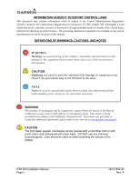
LIST OF FIGURES FIGURE PAGE Section 1 General Description 1-1 Section 2 Installation Overview 2-1 Section 3 Installation Procedures 3-1 Figure 3-1 GTR 200 Front Panel 3-4 Figure 3-2 Configuration Mode Home Page 3-5 Figure 3-3 COM Setup Page 3-7 Figure 3-4 ICS Sidetone Selection 3-8 Figure 3-5 Audio Setup Page (AUX and Music Disabled 3-9 Figure 3-6 Audio Setup Page (AUX and Music Enabled 3-9 Figure 3-7 Softkey Setup Page 3-10 Figure 3-8 Discrete Setup Page 3-11 Figure 3-9 Lighting Setup Page 3-12 Figure 3-10 Lighting Graph 3-13 Figure 3-11 Headset Tests Page 3-14 Figure 3-12 COM Tests Page 3-15 Figure 3-13 Audio Tests Page 3-16 Figure 3-14 About Page ...3-20 Figure 3-15 Software Update Page 3-20 Figure 3-16 MIcro SD Insertion 3-21 Figure 3-17 Software Update Page - Scanning Card 3-21 Figure 3-18 Software Update Page - No Update Found 3-22 Figure 3-19 Software Update Page - Update Software 3-22 Figure 3-20 Software Update Page - Preparing Update 3-22 Figure 3-21 Software Update Page - Unit Will Reboot 3-22 Section 4 Connector Pinout Information 4-1 Figure 4-1 J2001 Looking at rear of unit 4-1 Appendix A Shield Block Connector Installation Instructions A-1 Figure A-1 Shield Block Install onto a Backshell A-2 Figure A-2 Method A.1 for Shield Termination A-3 Figure A-3 Insulation/Contact Clearance A-5 Figure A-4 Method A.2 (Daisy Chain) for Shield Termination A-7 Figure A-5 Method B.1 (Quick Term) for Shield Termination A-8 Figure A-6 Method B.2 (Daisy Chain-Quick Term) for Shield Termination A-9 Figure A-7 Daisy Chain between Methods A and B A-10 Figure A-8 D-Sub Spliced Signal Wire illustration A-11 190-01553-00 Rev. A GTR 200 Installation Manual Page vii

  • 1
  • 2
  • 3
  • 4
  • 5
  • 6
  • 7
  • 8
  • 9
  • 10
  • 11
  • 12
  • 13
  • 14
  • 15
  • 16
  • 17
  • 18
  • 19
  • 20
  • 21
  • 22
  • 23
  • 24
  • 25
  • 26
  • 27
  • 28
  • 29
  • 30
  • 31
  • 32
  • 33
  • 34
  • 35
  • 36
  • 37
  • 38
  • 39
  • 40
  • 41
  • 42
  • 43
  • 44
  • 45
  • 46
  • 47
  • 48
  • 49
  • 50
  • 51
  • 52
  • 53
  • 54
  • 55
  • 56
  • 57
  • 58
  • 59
  • 60
  • 61
  • 62
  • 63
  • 64
  • 65
  • 66
  • 67
  • 68
  • 69
  • 70
  • 71
  • 72
  • 73
  • 74
  • 75

190-01553-00
GTR 200 Installation Manual
Rev. A
Page vii
LIST OF FIGURES
FIGURE
PAGE
Section 1
General Description
...........................................................................
1-1
Section 2
Installation Overview
.........................................................................
2-1
Section 3
Installation Procedures
......................................................................
3-1
Figure 3-1
GTR 200 Front Panel
..........................................................................................
3-4
Figure 3-2
Configuration Mode Home Page
........................................................................
3-5
Figure 3-3
COM Setup Page
.................................................................................................
3-7
Figure 3-4
ICS Sidetone Selection
........................................................................................
3-8
Figure 3-5
Audio Setup Page (AUX and Music Disabled)
..................................................
3-9
Figure 3-6
Audio Setup Page (AUX and Music Enabled)
....................................................
3-9
Figure 3-7
Softkey Setup Page
...........................................................................................
3-10
Figure 3-8
Discrete Setup Page
..........................................................................................
3-11
Figure 3-9
Lighting Setup Page
..........................................................................................
3-12
Figure 3-10
Lighting Graph
................................................................................................
3-13
Figure 3-11
Headset Tests Page
..........................................................................................
3-14
Figure 3-12
COM Tests Page
.............................................................................................
3-15
Figure 3-13
Audio Tests Page
............................................................................................
3-16
Figure 3-14
About Page
......................................................................................................
3-20
Figure 3-15
Software Update Page
.....................................................................................
3-20
Figure 3-16
MIcro SD Insertion
.........................................................................................
3-21
Figure 3-17
Software Update Page - Scanning Card
..........................................................
3-21
Figure 3-18
Software Update Page - No Update Found
.....................................................
3-22
Figure 3-19
Software Update Page - Update Software?
.....................................................
3-22
Figure 3-20
Software Update Page - Preparing Update
......................................................
3-22
Figure 3-21
Software Update Page - Unit Will Reboot
......................................................
3-22
Section 4
Connector Pinout Information
..........................................................
4-1
Figure 4-1
J2001 Looking at rear of unit
..............................................................................
4-1
Appendix A
Shield Block Connector Installation Instructions
.....................
A-1
Figure A-1
Shield Block Install onto a Backshell
..............................................................
A-2
Figure A-2
Method A.1 for Shield Termination
.................................................................
A-3
Figure A-3
Insulation/Contact Clearance
...........................................................................
A-5
Figure A-4
Method A.2 (Daisy Chain) for Shield Termination
.........................................
A-7
Figure A-5
Method B.1 (Quick Term) for Shield Termination
..........................................
A-8
Figure A-6
Method B.2 (Daisy Chain-Quick Term) for Shield Termination
......................
A-9
Figure A-7
Daisy Chain between Methods A and B
........................................................
A-10
Figure A-8
D-Sub Spliced Signal Wire illustration
..........................................................
A-11