Gateway MX6452 8511386 - Gateway Notebook Hardware Reference Guide - Page 55
With the back edge of the keyboard raised, carefully push it toward the LCD panel
 |
View all Gateway MX6452 manuals
Add to My Manuals
Save this manual to your list of manuals |
Page 55 highlights
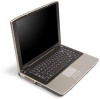
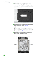
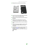
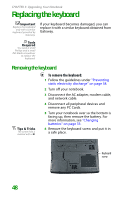
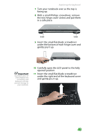
Replacing the keyboard 16 Loosen the mini-PCI bay cover screw (this screw cannot be removed), then remove the mini-PCI bay cover. Important Depending on the keyboard features, one of both of these screws may be absent. 17 Remove the two optional keyboard screws. Screw Screw 18 Turn your notebook over so the top is facing up, then open the LCD panel to the fully opened position. 19 With the back edge of the keyboard raised, carefully push it toward the LCD panel to release the keyboard retaining tabs. Be careful not to damage the LCD panel. 51
-
 1
1 -
2
-
3
-
4
-
5
-
6
-
7
-
8
-
9
-
10
-
11
-
12
-
13
-
14
-
15
-
16
-
17
-
18
-
19
-
20
-
21
-
22
-
23
-
24
-
25
-
26
-
27
-
28
-
29
-
30
-
31
-
32
-
33
-
34
-
35
-
36
-
37
-
38
-
39
-
40
-
41
-
42
-
43
-
44
-
45
-
46
-
47
-
48
-
49
-
 50
50 -
 51
51 -
 52
52 -
 53
53 -
 54
54 -
 55
55 -
 56
56 -
 57
57 -
 58
58 -
 59
59 -
 60
60 -
61
-
62
-
63
-
64
-
65
-
66
-
67
-
68
-
69
-
70
-
71
-
72
-
73
-
74
-
75
-
76
-
77
-
78
-
79
-
80
-
81
-
82
-
83
-
84
-
85
-
86
 |
 |

Replacing the keyboard
51
16
Loosen the mini-PCI bay cover screw (this
screw cannot be removed), then remove
the mini-PCI bay cover.
Important
Depending on the
keyboard features, one
of both of these screws
may be absent.
17
Remove the two optional keyboard screws.
18
Turn your notebook over so the top is
facing up, then open the LCD panel to the
fully opened position.
19
With the back edge of the keyboard raised,
carefully push it toward the LCD panel to
release the keyboard retaining tabs. Be
careful not to damage the LCD panel.
Screw
Screw