HP 3380 Service Manual
HP 3380 - LaserJet All-in-One B/W Laser Manual
 |
View all HP 3380 manuals
Add to My Manuals
Save this manual to your list of manuals |
HP 3380 manual content summary:
- HP 3380 | Service Manual - Page 1
hp LaserJet 3380 all-in-one service - HP 3380 | Service Manual - Page 2
- HP 3380 | Service Manual - Page 3
hp LaserJet 3380 all-in-one Service Manual - HP 3380 | Service Manual - Page 4
of injury from fire or electric shock. Read and understand all instructions in the user guide. Observe all warnings and instructions marked on the product. Use only a grounded electrical outlet when connecting the HP LaserJet 3380 all-in-one product to a power source. If you don't know whether the - HP 3380 | Service Manual - Page 5
...2 Hardware description ...2 Firmware description ...2 Software and supported operating systems 2 Product features HP's Premium Protection print-cartridge warranty 13 Extended warranty...14 Print-cartridge information ...15 Refilled print cartridges ...15 HP LaserJet printing supplies 15 HP - HP 3380 | Service Manual - Page 6
Life expectancies of parts that wear 48 Scanner calibration ...49 Cleaning the product ...50 Cleaning the glass...50 Cleaning the lid backing...51 Cleaning the paper path...51 Cleaning the print-cartridge area 52 Cleaning the pickup roller 54 Cleaning the printer separation pad 55 User - HP 3380 | Service Manual - Page 7
97 After performing service...98 Print cartridge ...98 Parts removal order ...98 Scanner assemblies ...101 Printer right-side cover 101 Scanner side covers ...102 Automatic document feeder (ADF) assembly 104 ADF pickup-roller assembly 105 ADF document-feed guide/cleanout comb 107 ADF input - HP 3380 | Service Manual - Page 8
6 Troubleshooting Basic troubleshooting ...161 Control-panel messages ...166 Alert and warning messages 166 Critical error messages 174 Event-log codes...177 Solving image-quality problems 179 Checking the print cartridge 179 Solving print image-quality problems 179 Solving scanning (copying - HP 3380 | Service Manual - Page 9
Ordering parts and supplies 250 Parts...250 Related documentation and software 250 Parts that wear ...250 Accessories...251 Memory...2. 51 Print cartridges and toner supplies 251 Cables...251 Common hardware ...252 Parts kits...253 How to use the parts lists and diagrams 253 Scanner assemblies - HP 3380 | Service Manual - Page 10
viii ENWW - HP 3380 | Service Manual - Page 11
9 HP LaserJet 3380 all-in-one fax specifications 10 HP LaserJet 3380 all-in-one battery 10 Control-panel menu structure 30 Supported media types 34 Common media problems 36 Life expectancies of parts that wear 48 Basic sequence of operation (printer 69 Basic sequence of operation (scanner 71 - HP 3380 | Service Manual - Page 12
Table 7-22. Table 7-23. Table 7-24. Table 7-25. Paper-pickup assembly (2 of 2 283 Fuser assembly 285 Alphabetical parts list 286 Numerical parts list 295 x ENWW - HP 3380 | Service Manual - Page 13
glass 50 Cleaning the scanner strip 51 Cleaning the lid backing 51 Unplug the product 52 Remove the print cartridge 53 Clean the print-cartridge cavity 53 Insert the print cartridge 53 Plug in the product 54 Inserting the pickup roller 54 Cleaning the printer separation pad (1 of 4 55 - HP 3380 | Service Manual - Page 14
switches 88 Remove the print cartridge 98 Parts removal order (1 of 2 99 Parts removal order (2 of 2 100 Remove the printer right-side cover (1 of 3 101 Remove the printer right-side cover (2 of 3 102 Remove the printer right-side cover (3 of 3 102 Remove the scanner right-side cover (1 of - HP 3380 | Service Manual - Page 15
Separate the scanner from the printer (3 of 4 120 Separate the scanner from the printer (4 of 4 121 Remove the height guides 122 Remove the left-side door 123 Remove the back cover (1 of 2 124 Remove the back cover (2 of 2 124 Remove the printer top cover 125 Remove the print-cartridge door - HP 3380 | Service Manual - Page 16
Using the firmware-recovery DIMM 215 Example of a T.30 trace of a successfully sent fax 236 Example of a T.30 trace of a successfully received fax 237 Main wiring (1 of 2 245 Main wiring (2 of 2 246 Locations of printer connectors 247 Locations of connectors and switches 248 Scanner and ADF - HP 3380 | Service Manual - Page 17
...2 Hardware description ...2 Firmware description ...2 Software and supported operating systems 2 Product HP's Premium Protection print-cartridge warranty 13 Extended warranty...14 Print-cartridge information ...15 Refilled print cartridges ...15 HP LaserJet printing supplies 15 HP - HP 3380 | Service Manual - Page 18
● Resolution Enhancement technology (REt) and EconoMode functionality Software and supported operating systems The following software components are included with the product: ● HP Toolbox ● HP LaserJet Scan ● TWAIN or WIA Scan Driver ● HP LaserJet Fax ● Readiris OCR (not installed with other - HP 3380 | Service Manual - Page 19
● Printer drivers (PCL 5e, PCL 6, and PS) ● Installer/uninstaller The following operating systems are supported: ● Windows 98Se (second edition) ● Windows Millennium Edition (Me) ● Windows 2000 ● Windows XP (32-bit) ● Mac OS 9.1 or 9.2.x ● Mac OS X (10.2.x only) ● Driver-only support for Windows 98 - HP 3380 | Service Manual - Page 20
features The HP LaserJet 3380 all-in-one is designed to perform the following tasks: ● Print: Print documents with HP LaserJet quality. ● Copy: Make up to 99 laser-quality copies of a 50-page original. It also enlarges, reduces, lightens/darkens, and collates copies. ● Scan: Scan documents to - HP 3380 | Service Manual - Page 21
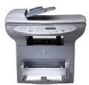
components (1 of 2) Figure 1-1. ENWW Product hardware components (2 of 2) 1 Automatic document feeder (ADF) input tray 2 Flatbed scanner lid 3 Product control panel 4 Output bin 5 Print-cartridge door 6 Priority input tray 7 Media input tray (also called the main input tray) 8 Left side panel - HP 3380 | Service Manual - Page 22
serial numbers The model number and serial number are listed on an identification label that is located on the inside of the print-cartridge door. The serial number contains information about the country/ region of origin, revision level, production code, and production number of the product. The - HP 3380 | Service Manual - Page 23
° to 40° C (-4° to 104° F) Humidity: Less than 95 percent relative humidity (no condensation) Performance Table 1-3. HP LaserJet 3380 all-in-one performance specifications Item Print resolution Scan resolution Print speed, letter-size paper Print speed, A4-size paper Copy speed, letter-size paper - HP 3380 | Service Manual - Page 24
HP LaserJet 3380 all-in-one performance specifications (continued) Item Value Printer minimum paper size 76 by 127 mm (3 by 5 inches) Printer maximum paper size 216 by 356 mm (8.5 by 14 inches) Printer subject to change. See http://www.hp.com/support/lj3380 for current information. 2 Note: - HP 3380 | Service Manual - Page 25
inaudible 1 Values subject to change. See http://www.hp.com/support/lj3380 for current information. During other operations, acoustic edge of the media, within the specifications. Table 1-6. HP LaserJet 3380 all-in-one skew specifications Category Specification Print skew-All vertical lines are - HP 3380 | Service Manual - Page 26
by the scanning software. The original document's size must be within the size ranges for the ADF or flatbed scanner. See Table 13. HP LaserJet 3380 all-in-one performance specifications for the size ranges. Battery specifications Table 1-8. HP LaserJet 3380 all-in-one battery Description - HP 3380 | Service Manual - Page 27
Table 1-8. HP LaserJet 3380 all-in-one battery (continued) Description Specification Battery type Button or coin cell battery (soldered to formatter, not replaceable) Quantity per unit 1 Weight Approximately 1 gram (0.04 ounce) Lithium - HP 3380 | Service Manual - Page 28
Warranty statement HP PRODUCT HP LaserJet 3380 all-in-one DURATION OF LIMITED WARRANTY One year from date of purchase. HP warrants to you, the end-user customer, that HP hardware, accessories, and supplies, will be free from defects in materials and workmanship after the date of purchase, for the - HP 3380 | Service Manual - Page 29
environmental specifications for the printer product or (c) exhibit wear from ordinary use. To obtain warranty service, please return the product to place of purchase (with a written description of the problem and print samples) or contact HP customer support. At HP's option, HP will either replace - HP 3380 | Service Manual - Page 30
can uplift the standard warranty, for example, from next-day to same-day service, and/or extend it up to 5 years. HP Care Pack can also provide Express Exchange or onsite service. For more information, see the support flyer that came with your device for the appropriate phone numbers and information - HP 3380 | Service Manual - Page 31
of HP LaserJet print cartridges influences the customer's perception of the product. Hewlett-Packard has no control over the actual print quality of a refilled cartridge. ● Parts that are critical to print quality might not be replaced when the cartridge is refilled with toner. HP LaserJet printing - HP 3380 | Service Manual - Page 32
Non-U.S. returns Non-U.S. customers should call the local HP Sales and Service office or visit the http://www.hp.com/recycle website for further information regarding availability of the HP Supplies Returns and Recycling program. 16 Chapter 1 Product information ENWW - HP 3380 | Service Manual - Page 33
B digital device, pursuant to Part 15 of the FCC rules. used in accordance with the instructions, it may cause harmful to try to correct the interference by one or more of the following measures: ● changes or modifications to the printer that are not expressly approved by HP could void the user's - HP 3380 | Service Manual - Page 34
may request you remove the equipment from the network until the problem is resolved. The following repairs can be done by the customer: Replace any original equipment that came with the product. This includes the print cartridge, the supports for trays and bins, the power cord, and the telephone - HP 3380 | Service Manual - Page 35
any other number for which charges exceed local or long-distance transmission charges.) In order to program this information into a fax, please see the fax guide. ENWW Telephone Consumer Protection Act (United States) 19 - HP 3380 | Service Manual - Page 36
an acceptable method of connection. The customer should be aware that compliance with the above conditions may not prevent degradation of service in some situations. Repairs to certified equipment should be coordinated by a representative designated by the supplier. Any repairs or alterations made - HP 3380 | Service Manual - Page 37
HP LaserJet 3380) or the product number (Q2660A). Boise, Idaho 83714, U.S.A. November 1, 2003 For regulatory topics only: Australia Contact Product Regulations Manager, Hewlett-Packard European Contact Your Local Hewlett-Packard Sales and Service Office or Hewlett-Packard Gmbh, Department HQ- - HP 3380 | Service Manual - Page 38
product under the U.S. Department of Health and Human Services (DHHS) Radiation Performance Standard according to the Radiation Control for Health and Safety Act of 1968. Since radiation emitted inside this printer is completely confined within protective housings and external covers, the laser - HP 3380 | Service Manual - Page 39
sätt än i bruksanvisning specificerats, kan användaren utsättas för osynlig laserstrålning, som överskrider gränsen för laserklass 1. HUOLTO HP LaserJet 3380 all-in-one-kirjoittimen sisällä ei ole käyttäjän huollettavissa olevia kohteita. Laitteen saa avata ja huoltaa ainoastaan sen huoltamiseen - HP 3380 | Service Manual - Page 40
compatibility is dependent on internal software settings. Contact your equipment supplier if it is necessary to use the equipment on a different telephone network. For further product support, contact Hewlett-Packard at the phone numbers provided in the support flyer that came with the product - HP 3380 | Service Manual - Page 41
HP LaserJet 3380 all-in-one. Operating environment ...26 Identifying the control-panel components 27 Fax controls ...27 Alphanumeric buttons ...28 Menu and cancel controls 28 Copy, scan or scan 43 To load originals onto the flatbed scanner 43 To load originals into the ADF input tray 43 Printer - HP 3380 | Service Manual - Page 42
Operating environment Place the product on a sturdy, level surface in a well-ventilated area that meets the following environmental requirements: ● temperature: 15° to 32.5° C (59° to 90.5° F) ● humidity: 10 to 80 percent relative humidity (no condensation) ● away from direct sunlight, open flames, - HP 3380 | Service Manual - Page 43
to send and receive faxes. These controls and the fax menu or software are used to change commonly used fax settings. For complete instructions about using the product's fax features, see the fax guide. Figure 2-2. Fax controls The product has extensive faxing capabilities. For a full description - HP 3380 | Service Manual - Page 44
control-panel display screen and to dial phone numbers for faxing. For a full description of using the alphanumeric buttons, see the fax guide. Figure 2-3. Alphanumeric buttons Menu and cancel controls Use these controls to select menu options, determine the product status, and cancel the current - HP 3380 | Service Manual - Page 45
used default settings, to start scanning, or to start copying. For instructions about copying, see "Copying" in the user guide. For instructions about scanning, see "Scanning" in the user guide. The user guide is on the product CD. Figure 2-5. Copy, scan, and start controls ENWW Identifying - HP 3380 | Service Manual - Page 46
MENU/ ENTER. 4. If applicable, use the < or > button to select one of the options from the second submenu, and then press MENU/ENTER. To print are currently selected, print a configuration report. See Troubleshooting tools for instructions. Table 2-1. Control-panel menu structure Main Menu - HP 3380 | Service Manual - Page 47
Table 2-1. Control-panel menu structure (continued) Main Menu Submenu Submenu Reports Demo Page Fax Activity log Print log now Auto Log Print Fax Call report Print report now Print report Include 1st page PhoneBook report Menu structure Config report Block Fax list Billing report Usage - HP 3380 | Service Manual - Page 48
Ring Type Extension Phone Silence Detect Fit to page Stamp faxes Forward fax Block faxes Add entry Delete entry Clear all All faxes Error correction V.34 Common settings Language Def. Paper Size Print Density Volume settings Alarm volume Ring volume Key Press volume PhoneLine Volume 32 - HP 3380 | Service Manual - Page 49
Table 2-1. Control-panel menu structure (continued) Main Menu Submenu Submenu Service Print T.30 trace Restore defaults Cleaning Mode Power Save time Less paper curl Submenu ENWW Control-panel menu structure 33 - HP 3380 | Service Manual - Page 50
does not meet HP's specifications is not covered by the HP warranty or service agreements. Note Supported media sizes and types The printer supports media within this supports and the associated fuser mode. Narrow and heavy media can cause the printer to print more slowly. Table 2-2. Supported - HP 3380 | Service Manual - Page 51
Table 2-2. Supported media types (continued) Media type Fuser mode Rough Thick Unspecified Uses default setting ENWW Product media specifications 35 - HP 3380 | Service Manual - Page 52
or problems with feeding. Too moist, wrong grain direction, or short-grain construction. Use long-grain paper. Print using the straight-through output path. For copy or fax jobs, select less paper curl in the service menu. For print jobs, select a lighter-weight media type from the printer driver - HP 3380 | Service Manual - Page 53
Jamming, or damage to printer. Cutouts or perforations. Problems with feeding. Ragged edges. Solution Do not use media that has cutouts or perforations. Use good-quality media. Labels For best results, use only HP-brand labels. To order HP supplies, visit http://www.hp.com. When selecting - HP 3380 | Service Manual - Page 54
adhesive strip or with more than one flap that folds over to seal must use adhesives or 392° F) and pressure in the printer. The extra flaps and strips might cause that is too heavy might cause misfeeds, stacking problems, jams, poor toner fusing, poor print quality, or excessive mechanical wear - HP 3380 | Service Manual - Page 55
● Condition: Make sure that the card stock is not wrinkled, nicked, or otherwise damaged. ● Sizes: Use only card stock within the following size range: - Minimum: 76 by 127 mm (3 by 5 inches) - Maximum: 216 by 356 mm (8.5 by 14 inches) Card stock guidelines ● If the card stock curls or jams, use the - HP 3380 | Service Manual - Page 56
This helps prevent multiple sheets of media from feeding through the printer at one time, reducing jams. Specific types of media ● Transparencies and forward and the side to be printed on facing up. See the user guide on the product CD for more information. ● Letterhead and preprinted forms: Load - HP 3380 | Service Manual - Page 57
Use either the ADF or the flatbed scanner for most copying, scanning, and faxing needs. Specifications for ADF ink. ● Do not insert gum-backed paper or labels. ● Avoid multiple-copy forms. ● Do not scan originals that are larger or smaller than supported size limitations. See the user guide - HP 3380 | Service Manual - Page 58
faxing if the media is fragile, thin, thick, or damaged (folded, wrinkled), or to produce a high-quality copy or file. The flatbed scanner provides the best copy and scan quality. The flatbed has no minimum size specification, and accepts a maximum size of legal-size media (215.9 mm by 355.6 mm, or - HP 3380 | Service Manual - Page 59
to copy or scan Use these instructions to load originals into the product for copying or scanning. For the bestquality scans and copies, use the flatbed scanner. See Selecting originals for the automatic document feeder (ADF) for guidelines to choose original documents for scanning and copying. To - HP 3380 | Service Manual - Page 60
4. Adjust the media guides until they are snug against the sides of the stack. 5. The document is now ready to be copied or scanned. 6. After scanning, the document is delivered to the output tray in the correct order. 44 Chapter 2 Operation ENWW - HP 3380 | Service Manual - Page 61
Printer output paths The HP LaserJet 3380 all-in-one has two output paths. Use the main output printed. Output bin and straight-through output path The output bin is located between the scanner and the printer. Printed media is collected here in the correct sequence when the straight-through output - HP 3380 | Service Manual - Page 62
46 Chapter 2 Operation ENWW - HP 3380 | Service Manual - Page 63
topics. Life expectancies of parts that wear 48 Scanner calibration ...49 Cleaning the product ...50 Cleaning the glass...50 Cleaning the lid backing...51 Cleaning the paper path...51 Cleaning the print-cartridge area 52 Cleaning the pickup roller 54 Cleaning the printer separation pad 55 User - HP 3380 | Service Manual - Page 64
that wear Description Print cartridge1 (userreplaceable) Part number C7115A C7115X Life (estimated) 2,500 pages 3,500 pages Remarks When print becomes faint, redistribute toner in the cartridge by gently shaking the cartridge from side to side. Printer transfer roller RM1-0550-000CN 50,000 - HP 3380 | Service Manual - Page 65
itself automatically at the start of scan of copy jobs. Normally, you do not need to initiate the calibration, but you can initiate the calibration through the secondary service menu and produce a report that shows the calibration results. See Secondary service menu. ENWW Scanner calibration 49 - HP 3380 | Service Manual - Page 66
free cloth (such as a lens tissue). To avoid permanent damage to the print cartridge, do not use ammonia-based or ethyl alcohol-based cleaners on or around the product. Avoid touching the heating element in the fuser alcohol, or carbon tetrachloride on any part of the product; these can damage the - HP 3380 | Service Manual - Page 67
has been moistened with nonabrasive glass cleaner. Figure 3-2. Note Cleaning the scanner strip 4. Dry the glass with a chamois or cellulose sponge to this cannot be cleaned, and it has no effect on the copy or scan quality. Cleaning the lid backing Minor debris can accumulate on the white document - HP 3380 | Service Manual - Page 68
the product. Over time, this buildup can cause print-quality problems, such as toner specks or smearing. To correct and prevent these types of problems, you can clean the print-cartridge area and the media path. To clean the print-cartridge area Wait for the product to cool before beginning this - HP 3380 | Service Manual - Page 69
. 3. Use a dry, lint-free cloth, or an HP toner cloth (part number 5090-3379) to wipe any residue from the paper-path area and the print-cartridge cavity. Figure 3-6. Clean the print-cartridge cavity 4. Replace the print cartridge, and close the print-cartridge door. Figure 3-7. Insert the print - HP 3380 | Service Manual - Page 70
always a dirty or worn separation pad. See Cleaning the printer separation pad for instructions. If the product is feeding multiple transparencies at one time, the pickup roller is probably not the cause. See Solving print paper-feed problems for more information. To clean the pickup roller Remove - HP 3380 | Service Manual - Page 71
pad rather than replace it, use the following instructions. 1. Remove the separation pad as described in steps 1 through 5 of Replacing the printer separation pad. Figure 3-10. WARNING! Cleaning the printer separation pad (1 of 4) 2. Dampen a lint-free cloth with isopropyl alcohol, and scrub the - HP 3380 | Service Manual - Page 72
parts. Replacing the pickup roller If the product does not pick up media from the tray, the cause is almost always a dirty or damaged pickup roller. If cleaning the pickup roller does not resolve the problem, replace the pickup roller. CAUTION To replace the pickup roller Failure to complete - HP 3380 | Service Manual - Page 73
up and out. Figure 3-18. Replacing the pickup roller (5 of 9) 6. Position the new or cleaned part in the slot that held the pickup roller previously. See Cleaning the pickup roller for instructions. Figure 3-19. Note Replacing the pickup roller (6 of 9) Circular and rectangular pegs on each side - HP 3380 | Service Manual - Page 74
does not resolve the problem, replace the printer separation pad. Recurring feed problems indicate that the printer separation pad is worn. Before you replace the separation pad, clean the pickup roller. See Cleaning the pickup roller for instructions. To replace the printer separation pad 1. Use - HP 3380 | Service Manual - Page 75
separation pad and twist until the tabs are free. Figure 3-26. CAUTION Replacing the printer separation pad (4 of 9) Touching the black one hand, and pull the separation pad up (2) with the other hand. Figure 3-27. Replacing the printer separation pad (5 of 9) ENWW User-replaceable parts - HP 3380 | Service Manual - Page 76
or if space exists on one side, remove the separation pad, make sure that the larger tab is on the right, reinsert the separation pad, and snap both sides into place. 8. Reinsert the print cartridge, and close the print-cartridge door. Figure 3-30. Replacing the printer separation pad (8 of 9) 60 - HP 3380 | Service Manual - Page 77
printer separation pad (9 of 9) If the pad is not properly positioned, the product might be noisy or the media might not feed at all. Replacing an ADF If the automatic document feeder (ADF) jams repeatedly, see Troubleshooting to try to resolve the problem. If necessary, follow these instructions - HP 3380 | Service Manual - Page 78
, do not allow the ADF lid to fall onto the flatbed scanner. Always close the ADF lid when the product is not in trouble picking paper, see Troubleshooting to try to resolve the problem. If necessary, replace the ADF pickup-roller assembly. To remove the existing assembly, follow these instructions - HP 3380 | Service Manual - Page 79
roller assembly should remain on the black surface. Figure 3-40. Replacing the ADF pickup-roller assembly (3 of 9) 4. Remove the old assembly and put the new one in exactly the same place. The largest roller goes in back, and the gear side is away from you. Figure 3-41. Replacing the ADF pickup - HP 3380 | Service Manual - Page 80
5. Lower the green lever so that the flat green part fits between the rollers. Press down on the green lever until you hear it snap into place. . Note Replacing the ADF pickup-roller assembly (8 of 9) If you are experiencing jams in the ADF, see Troubleshooting. 64 Chapter 3 Maintenance ENWW - HP 3380 | Service Manual - Page 81
9) Removing and replacing the product control-panel bezel The control-panel bezel is available in several languages. To order a different bezel, see Ordering parts and supplies. To replace the product control-panel bezel 1. Use the power switch to turn off the product, and then unplug the power cord - HP 3380 | Service Manual - Page 82
3. Align the tab in the center of the bottom of the bezel with the slot on the product. Figure 3-49. Replacing the control-panel bezel (3 of 4) 4. Press the bottom of the bezel onto the product, and then continue to press while pushing your hands up toward the top of the bezel until it snaps into - HP 3380 | Service Manual - Page 83
overview This chapter contains information about the following topics. Basic functions ...68 Basic sequence of operation (formatter-to-printer 69 Basic sequence of operation (scanner 71 Formatter system ...73 Central processing unit ...73 Line interface unit (LIU) ...73 Motor controller PCA ...73 - HP 3380 | Service Manual - Page 84
a functional overview of the HP LaserJet 3380 all-in-one. The following systems are discussed: ● printer functions and operation - engine controller unit (ECU) system/power system - laser/scanner system - image-formation system - paper-feed system (printer) and document-feed system (document - HP 3380 | Service Manual - Page 85
printer) Period Purpose Remarks WAIT. After the product is turned To clear the drum surface of on until the end of the initial potential and to clean the rotation of the main motor. primary charging roller. Detects whether or not the cartridge and to transfer the toner image onto the media. - HP 3380 | Service Manual - Page 86
The timing diagram in Figure 4-2. Printer timing diagram illustrates which components are affected during each of the periods in the basic sequence of operation for the printer. Figure 4-2. Printer timing diagram 70 Chapter 4 Operational overview ENWW - HP 3380 | Service Manual - Page 87
Scanner Bulb warming up appears on the control-panel display. To perform the firmware end) if the scanner bulb does not warm up within 2 minutes, and an error message appears on after the last scanner usage (copy/scan/ fax). To reduce power consumption and increase scanner bulb life. POWERSAVE - HP 3380 | Service Manual - Page 88
. STAGE. From the end of CALIBRATION until the SCAN period. For an ADF scan: to position the scanner under the ADF scanning window, and then to position the original document's leading edge at the scanning position. For a flatbed scan: to position the scanner at the documentorigin position before - HP 3380 | Service Manual - Page 89
printer interface ● monitoring the control panel and relaying printer motor-driver circuitry firmware code to be recovered or updated. The firmware update and recovery process is described in Troubleshooting. Standard boot process When the product is unplugged or the power is off, the firmware - HP 3380 | Service Manual - Page 90
chapter 6). Contact Service Control-code failure. The flash memory requires a DIMM recovery of the firmware code (see chapter 6). Hewlett-Packard - HP 3380 | Service Manual - Page 91
HP so that you can return to the software program more quickly. The EIO feature one page and the bottom half on the next page). Some print-data loss is likely in these instances, and an error message will appear on the control-panel display. PJL overview Printer job language (PJL) is an integral part - HP 3380 | Service Manual - Page 92
to the next raster line. If the flatbed is being used, the scanner module advances to the next raster line. This advancing and collection process LIU as a fax, or directing it to the computer as scanner output. The image data collected for scans is 600 pixels per inch (ppi). The image data collected - HP 3380 | Service Manual - Page 93
scan is initiated (from the software or the control panel), the scan module moves to the left side of the scan tub and stops. The image is acquired as the paper is fed through the ADF past the scanner the scanner to start when the page reaches the glass. The scanner acquires the image, one raster - HP 3380 | Service Manual - Page 94
The form sensor detects the top and bottom edges of the document. One other sensor detects an open ADF door. ADF jam detection The ADF the paper stops in the ADF and the scan module remains under the ADF scanner glass, an internal firmware error has probably occurred. This is usually remedied by - HP 3380 | Service Manual - Page 95
diagram of the printer and its relationship to the ADF/scanner and LIU. ADF Scanner system Face-down bin Motor controller Control Panel LIU Computer LASER/SCANNER Scanning mirror Formatter Face-up bin Laser diode BD sensor Scanner motor ENGINE CONTROL SYSTEM ECU Fuser Cleaning unit - HP 3380 | Service Manual - Page 96
- dc power distribution - high-voltage power distribution - low-voltage power distribution ● Paper motion and monitoring ● Motors - main motor (M1) - fan motor (FN1) ● Printer laser/scanner ● Image formation ● Fuser - temperature control - failure detection 80 Chapter 4 Operational overview ENWW - HP 3380 | Service Manual - Page 97
to the ac power source. Ac voltage is distributed to the dc power supply circuitry and to the ac driver circuitry, which controls ac voltage to the fuser assembly heating element. Dc power distribution The dc power distribution circuitry, located on the ECU, distributes +3.3 Vdc, +5 Vdc, +24 - HP 3380 | Service Manual - Page 98
Printer paper-path motor Exhaust fan Laser/scanner motor Solenoid Formatter (routing only) High-voltage power supply Fuser safety circuit Scanner (CCD) ● +32 Vdc: ADF motor Scanner transfer roller according to the instructions from the engine control unit. 82 Chapter 4 Operational overview ENWW - HP 3380 | Service Manual - Page 99
circuit Low-voltage power distribution The low-voltage power supply circuit converts ac power into +24 Vdc, +5 Vdc, and +3.3 Vdc as required by the printer. The +24 Vdc is divided into +24 V, which is supplied constantly from the low-voltage power supply circuit, and +24 U, which is supplied to - HP 3380 | Service Manual - Page 100
. Motors The ECU controls the motors. The main motor provides all of the paper movement in the printer. The fan motor rotates the fan to cool the printer. Printer laser/scanner drive The laser/scanner system is controlled by the ECU, which sends laser control signals CNT0, CNT1, and CNT2, and by - HP 3380 | Service Manual - Page 101
coordinated with the other printer processes. Image formation charging roller, which is located in the print cartridge. The primary-charging roller is coated with conductive scan line of data. 3. Developing stage-During this process, the latent electrostatic image is present on the drum. The toner - HP 3380 | Service Manual - Page 102
Protect the print cartridge whenever you remove it. Printer paper-feed system The main input tray and the priority input tray merge into one main input area. the media enters the fuser assembly, where heat from the fuser and pressure from the pressure roller permanently bond the toner image to media. - HP 3380 | Service Manual - Page 103
priority input tray or the main input tray. The paper-top sensor (PS911) and the paper-delivery sensor (PS921) detect media moving through the printer. If a jam is detected, the ECU immediately stops the printing process and a jam message appears on the control-panel display. A jam can be detected - HP 3380 | Service Manual - Page 104
rotation period. ● Door open jam-The paper-top sensor (PS911) or the paper-delivery sensor (PS921) detect media while the print-cartridge door is open. Solenoid, photosensors, and switches The following figure shows the locations of the solenoid, photosensors, and switches. Figure 4-11. Solenoid - HP 3380 | Service Manual - Page 105
is completed, the software all contribute to the fax functionality. The designs of the formatter and LIU, along with parameters in the firmware, determine the majority of the regulatory requirements for telephony on the product. The fax subsystem is designed to support HP LaserJet 3380 all-in-one. One - HP 3380 | Service Manual - Page 106
The following are features that are different in the European version: ● a different voltage-protection device ● current limiting of the dc current ● filtering for the countries/regions that use billing or metering tones ● control of the impedance of the dc circuit through the SHUNT signal Because - HP 3380 | Service Manual - Page 107
unless it detects a fax tone or the operator tells it to connect manually. This feature allows the user to make voice calls from a phone that detection The aux phone detect signal is optically coupled. This signal tells the firmware that an active phone (or modem or answering machine) is connected to - HP 3380 | Service Manual - Page 108
such an event, the firmware tells the DSP on the created in any of three ways: scanned to be sent to another fax for the file system and reclamation. Adding RAM does not affect the fax page cartridge runs out of toner or the product experiences other errors while printing faxes. 92 Chapter - HP 3380 | Service Manual - Page 109
memory before a fax job is sent. This allows the sender to pick up their original document immediately after it is scanned, eliminating the need to wait until the fax is transmission is complete. Because fax pages are stored in flash memory, not RAM, more RAM is available to handle larger and more - HP 3380 | Service Manual - Page 110
94 Chapter 4 Operational overview ENWW - HP 3380 | Service Manual - Page 111
97 After performing service...98 Print cartridge ...98 Parts removal order ...98 Scanner assemblies ...101 Printer right-side cover 101 Scanner side covers ...102 Automatic document feeder (ADF) assembly 104 ADF pickup-roller assembly 105 ADF document-feed guide/cleanout comb 107 ADF input - HP 3380 | Service Manual - Page 112
To reinstall the paper lift-plate assembly 148 Right plate assembly ...149 Left plate assembly ...150 Bottom assemblies ...152 ECU fuses and ECU pan 152 Paper-feed assembly ...155 96 Chapter 5 Removal and replacement ENWW - HP 3380 | Service Manual - Page 113
to service the product. If this warning is not followed, severe injury can result. Certain functional checks during troubleshooting must process. For service purposes, the upper part of the HP LaserJet 3380 all-in-one is, in effect, the "scanner" and the lower part is the "printer." Together, - HP 3380 | Service Manual - Page 114
Remove the print cartridge Parts removal order Use the following diagrams to determine which parts must be removed before removing other parts. 1. Locate the part that you want to remove on one of the diagrams. 2. If the part is on the first diagram, separation of the printer from the scanner is not - HP 3380 | Service Manual - Page 115
, you are required to separate the scanner from the printer before removing the part. Scanner/printer separation not required: ADF pickup-roller assembly ADF document-feed guide/cleanout comb ADF separation pad height guides transfer roller LIU ADF lid ADF scanner glass and frame control-panel bezel - HP 3380 | Service Manual - Page 116
other ADF submechanisms. top cover laser/scanner assembly height flapper left and right support covers transfer upper-guide assembly (left-side door, right-side cover, top cover) fuser output rollers solenoid and fan (print-cartridge door, front cover, front-guide assembly) right-plate assembly and - HP 3380 | Service Manual - Page 117
assemblies The parts described in this section can all be removed without separating the scanner from the printer. Printer right-side cover 1. Open the print-cartridge door. 2. Open the straight-through output door. 3. Remove one screw (callout 1). 1 Figure 5-4. Remove the printer right-side - HP 3380 | Service Manual - Page 118
separate the cover from the product, and then pull it towards the back of the product to remove it. Figure 5-6. Remove the printer right-side cover (3 of 3) Scanner side covers 1. Remove the printer right-side cover. See Printer right-side cover. 102 Chapter 5 Removal and replacement ENWW - HP 3380 | Service Manual - Page 119
Remove the two screws (callout 1) that fasten the scanner right-side cover in place. 1 Figure 5-7. Remove the scanner right-side cover (1 of 2) 3. Slide the cover toward the back of the product, and remove it. Figure 5-8. Remove the scanner right-side cover (2 of 2) ENWW Scanner assemblies 103 - HP 3380 | Service Manual - Page 120
Open the print cartridge door and the left-side door to expose the screws (callout 2) that hold the scanner left side cover. 2 Figure 5-9. Remove the left-side scanner cover (1 of 2) 5. Slide the cover toward the back of the product, and remove it. Figure 5-10. Remove the left-side scanner cover - HP 3380 | Service Manual - Page 121
and document-feed guide/cleanout comb are userreplaceable parts, but the ADF separation pad is not. Instructions for replacing the pickuproller assembly and the document-feed guide/cleanout comb appear in chapter 3 of this manual and are repeated here. If the ADF has trouble picking paper, the - HP 3380 | Service Manual - Page 122
2. Press the round, green button (callout 1) while lifting the green lever (callout 2). Rotate the green lever until it stops in the open position. The pickup-roller assembly will remain on the black surface. 1 2 Figure 5-13. Remove the ADF pickup-roller assembly (2 of 5) 3. Remove the pickup- - HP 3380 | Service Manual - Page 123
4. Lower the green lever until the flat, green part fits between the rollers. Press down on the pickup roller frame until the assembly 4). 4 Figure 5-16. Remove the ADF pickup-roller assembly (5 of 5) ADF document-feed guide/cleanout comb 1. Open the ADF door. ENWW Scanner assemblies 107 - HP 3380 | Service Manual - Page 124
2. Unsnap the ADF document-feed guide/cleanout-comb one side at a time, and then gently pull the guide back to remove it. Figure 5-17. Remove the ADF document-feed guide/cleanout comb Reinstallation tip Make sure that both sides of the ADF document-feed guide/cleanout comb snap into place. - HP 3380 | Service Manual - Page 125
positioning of the ADF input-tray spring ADF separation pad 1. Open the ADF door. Use the green lever to raise the pickup-roller assembly. ENWW Scanner assemblies 109 - HP 3380 | Service Manual - Page 126
2. Use a #8 torx driver to remove the two screws that secure the ADF separation pad separation pad. Skin oils and fingerprints can contaminate the glass or pad and cause print-quality problems or paper-pickup problems. Control-panel bezel 1. Remove the control-panel bezel by lifting up on the edges - HP 3380 | Service Manual - Page 127
to press while pushing up toward the top of the bezel until it snaps into place. Figure 5-24. Reinstall the control-panel bezel (2 of 2) ENWW Scanner assemblies 111 - HP 3380 | Service Manual - Page 128
Control panel 1. Four sliding tabs are at the top of the control panel. The second tab from the right locks into place. Use a small flat-blade screwdriver to press down on the locking portion of the snap-fit that holds the tab (callout 1), and slide the control panel to the right while pressing down - HP 3380 | Service Manual - Page 129
shown in Figure 5-25. Remove the control panel (1 of 2). Control-panel chassis 1. Remove three screws (callout 1). 1 Figure 5-27. Remove the control-panel chassis (1 of 2) ENWW Scanner assemblies 113 - HP 3380 | Service Manual - Page 130
The speaker and control-panel cable are both replaceable parts. Make sure that the controlpanel cable and speaker cable are correctly routed when reinstalled. Align the bottom guides on the control-panel chassis with the slots on the scanner assembly (callout 2). Push the control-panel chassis in - HP 3380 | Service Manual - Page 131
the speaker cable (callout 2) from the back of the control-panel chassis, and slide the speaker out (callout 3). 23 Figure 5-31. Remove the speaker (2 of 2) Scanner PCA 1. Remove the left scanner cover. See Scanner side covers. ENWW Scanner assemblies 115 - HP 3380 | Service Manual - Page 132
2, and remove the wire that it holds in place. 4. Remove the two screws shown in callout 3, and then remove the scanner PCA. 2 3 Figure 5-33. Note Remove the scanner PCA (2 of 3) If the scanner and printer are not separated, disconnect the two FFCs at the top of the formatter before removing the - HP 3380 | Service Manual - Page 133
CAUTION Do not bend or fold the FFCs during the removal or reinstallation process. 4 Figure 5-34. Remove the scanner PCA (3 of 3) ENWW Scanner assemblies 117 - HP 3380 | Service Manual - Page 134
fingerprints can contaminate the glass or pad and cause print-quality problems. 1. Remove one screw (callout 1), lift out the plastic ADF scanner-glass frame, and then lift out the glass. 1 Figure 5-35. Remove the ADF scanner glass Reinstallation tip Replace the glass first, and then install the - HP 3380 | Service Manual - Page 135
Separation of the scanner from the printer CAUTION The upper part of the HP LaserJet 3380 is, in effect, the "scanner" and the lower part is the "printer." Together, they also act as a photocopier or fax machine, but the service description here is simplified by referring to copier or fax - HP 3380 | Service Manual - Page 136
FFCs at the top of the formatter (callout 3). Do not bend or fold the FFCs during the removal or reinstallation process. 2 3 Figure 5-38. Separate the scanner from the printer (2 of 4) 4. Remove the two screws from the back of the product (callout 4). 4 Figure 5-39. Separate the - HP 3380 | Service Manual - Page 137
5. Slide the scanner toward the front of the product, and lift it upward to separate it from the printer. Figure 5-40. Separate the scanner from the printer (4 of 4) ENWW Separation of the scanner from the printer 121 - HP 3380 | Service Manual - Page 138
in the section for separating the scanner from the printer. See Printer right-side cover. Height guides This procedure can be completed without separating the scanner and printer. For clarity only, the following steps show the scanner and printer separated. 1. Use a short, flat-blade screwdriver - HP 3380 | Service Manual - Page 139
door 3. Lift the door away. Back cover 1. Remove the right-side cover (see Printer right-side cover), and open or remove the leftside door (see Left-side door). the left-side door, but removing the back cover removes the support for the left-side door, which leaves it vulnerable to breakage. 2. - HP 3380 | Service Manual - Page 140
the back cover (1 of 2) The back cover has two tabs (not shown): one on the side of the printer, and one on the bottom of the printer. You can use a screwdriver to press on the side tab. 4. Press down and hold the two fuser release levers (callout 2), and pull off the back cover. 2 Figure 5-44 - HP 3380 | Service Manual - Page 141
top cover 1. Separate the printer from the scanner (see Separation of the scanner from the printer). Remove the left-side door, right-side cover, and back cover (see External components), and open the print cartridge door. 2. Remove two screws on the sides of the printer (callout 1). Remove the four - HP 3380 | Service Manual - Page 142
callout 1) and disconnect them. 1 Figure 5-46. CAUTION Remove the print-cartridge door (1 of 2) If the link arms fall back into or are pushed back into the printer when they are disconnected from the print-cartridge door, the interlocking mechanism might come apart and require reassembly. To avoid - HP 3380 | Service Manual - Page 143
2. Loosen two screws (one shown, callout 1), one on each side of the cover. 1 Figure 5-48. Remove the front cover (1 of 2) 3. Push down on both the top-center and bottom-center of the - HP 3380 | Service Manual - Page 144
to guard against breakage (callout 2). 2 Figure 5-50. Front cover removed Front guide assembly 1. Open the left-side door and remove the right cover (see Printer right-side cover), the print-cartridge door (see Print-cartridge door), and the front cover (see Front cover). 2. From the front of - HP 3380 | Service Manual - Page 145
the lower tab (callout 3). 2 3 Figure 5-52. Remove the front guide assembly (2 of 3) 4. On the left side, release the upper tab (callout 2) and the lower tab (callout 3). 5. Remove the front guide assembly. 4 5 Figure 5-53. Remove the front guide assembly (3 of 3) ENWW External components 129 - HP 3380 | Service Manual - Page 146
assemblies CAUTION This section includes procedures to remove the major internal printer assemblies. Laser/scanner assembly 1. Remove the printer top cover (see Printer top cover). 2. Remove one connector (callout 1), one FFC (callout 2), and four screws (callout 3). Do not bend or fold the - HP 3380 | Service Manual - Page 147
side down (into the printer) and firmly press down until it snaps over the center of the face-down roller shaft. Left and right support covers (front corner brackets) 1. Remove the two screws holding the left support cover (callout 1) and one screw holding the right support cover (callout 2). Lift - HP 3380 | Service Manual - Page 148
guide assembly up and out of the printer. Reinstallation tip When installing the transfer upper guide assembly, install the right-side of the guide this grounding spring. 1. Open the print-cartridge door, and remove the print cartridge (see Print cartridge). 2. Use needle-nose pliers to gently - HP 3380 | Service Manual - Page 149
roller up, slide it to the right, and lift it out of the printer. Figure 5-58. CAUTION Remove the transfer roller Line interface unit (LIU) 1. Open or remove the left-side door (see Left-side door). 2. Remove one screw (callout 1) at the left of the formatter board. 3. Disconnect the flat flexible - HP 3380 | Service Manual - Page 150
Note 5. To separate the LIU PCA from the cover, turn the LIU over, remove the screw (callout 3), and then pry the tabs open (callout 4). Slide the LIU PCA out of the cover. Be careful not to misplace the LIU groundstrap (callout 5). 3 4 5 Figure 5-60. Note Remove the LIU (2 of 2) Formatter - HP 3380 | Service Manual - Page 151
disconnect the FFC (callout 1). Along the top of the formatter, disconnect the three FFCs and one wire connector (callout 2) . Do not bend or fold the FFCs during the removal or and remove it. Left bottom frame support 1. Open the left-side door. 2. Remove the formatter. See Formatter. ENWW - HP 3380 | Service Manual - Page 152
1 Figure 5-63. Remove the left bottom frame support 4. Remove the left bottom frame support. Fuser assembly 1. Separate the scanner from the printer (see Separation of the scanner from the printer) and remove the left side door, back cover, and printer top cover (see Left-side door, Back cover - HP 3380 | Service Manual - Page 153
-roller gear. Release the tab (callout 3), and remove the pressure-roller gear. 1 2 3 Figure 5-64. Remove the fuser assembly (1 of 4) 4. Remove three screws (callout 4) from the left-side fuser plate and remove it. 4 Figure 5-65. Remove the fuser assembly (2 of 4) ENWW Printer assemblies 137 - HP 3380 | Service Manual - Page 154
5. Remove two screws (one shown in callout 5), one from each side of the printer. 5 Figure 5-66. Note Remove the fuser assembly (3 of 4) 6. Unplug the fuser cable connector (callout 6) by pressing and releasing the tab on the back of the connector. 7. Remove one screw (callout 7) from the paper- - HP 3380 | Service Manual - Page 155
10. Pull the printer frame outward on both sides, and gently lift out the fuser assembly. The left and right fuser plates are detached when the fuser is removed. 7 6 8 9 Figure 5-67. Remove the fuser assembly (4 of 4) Reinstallation tip Remove the large gear from the end of the fuser assembly, - HP 3380 | Service Manual - Page 156
rollers (1 of 2) Face-up roller (output roller) 1. Turn the fuser assembly over. 2. Remove the gear (callout 1) from the face-up roller the face-up roller away from the gear side, and lift it out of the fuser assembly. 1 2 Figure 5-69. Remove the output rollers (2 of 2) Reinstallation tip - HP 3380 | Service Manual - Page 157
the printer (see Separation of the scanner from the printer), and remove the left-side door and back cover (see Left-side door and Back cover). 2. Unplug five cable connectors (callout 1) from the ECU, and unwind the bundle of cables. 3. Carefully unwind the cables from the cable guides (callout - HP 3380 | Service Manual - Page 158
you have trouble rerouting the cables through the hole (callout 2) in the right-side plate, remove the ECU pan (see ECU fuses and ECU pan) before rerouting the cables through the hole. Fan assembly 1. Separate the scanner from the printer (see Separation of the scanner from the printer ) and remove - HP 3380 | Service Manual - Page 159
3. Carefully unwind the cables from the cable guides (callout 2). Figure 5-73. Remove the fan (1 of 2) 4. Remove the fan assembly. Figure 5-74. Remove the fan (2 of 2) Reinstallation tip If you have trouble rerouting the cables through the hole (callout 4) in the right-side plate, remove the ECU - HP 3380 | Service Manual - Page 160
Pickup assembly 1. Remove the right-side cover, print-cartridge door, front cover, front-guide assembly, and formatter (see Printer right-side cover, Front-cover assembly, Front guide assembly, and Formatter). 2. Remove one screw (callout 1). 1 Figure 5-75. Remove the pickup assembly (1 of 3) 3. - HP 3380 | Service Manual - Page 161
assembly (3 of 3) Paper lift-plate assembly and pickup roller shaft 1. Remove the front cover, print-cartridge door, and front guide assembly (see Front-cover assembly, Print-cartridge door, and Front guide assembly). 2. Remove the pickup assembly (see Pickup assembly). ENWW Printer assemblies 145 - HP 3380 | Service Manual - Page 162
CAUTION 3. Remove the solenoid clutch gears (callout 1) by releasing the locking tab inside of the printer (callout 2) and sliding the gears off of the shaft and away from the left side of the product. The solenoid clutch gear assembly is made - HP 3380 | Service Manual - Page 163
5. Carefully angle the left end of the shaft toward the back of the product. Figure 5-80. Remove the paper lift-plate assembly (3 of 4) 6. Flip up the paper lift-plate and lift it straight up to remove it. Figure 5-81. Remove the paper lift-plate assembly (4 of 4) ENWW Printer assemblies 147 - HP 3380 | Service Manual - Page 164
7. If you want to remove the pickup roller shaft, carefully angle the left side outward. Figure 5-82. Remove the pickup roller shaft Reinstallation tip Be sure that the clutch on the pickup roller shaft is aligned with the follower (the large plastic tab) on the paper lift-plate. To reinstall the - HP 3380 | Service Manual - Page 165
scanner from the printer (see Separation of the scanner from the printer), and remove the left-side door and back cover (see Left-side door and Back cover). 2. Remove the front cover, print-cartridge door, and front guide the fuser, remove the fuser screw and the largest gear on the fuser (these - HP 3380 | Service Manual - Page 166
2) Left plate assembly 1. Separate the scanner from the printer (see Separation of the scanner from the printer), and remove the left-side door and back cover (see Left-side door and Back cover). 2. Remove the front cover, the print-cartridge door, and the front guide assembly (see pages Front-cover - HP 3380 | Service Manual - Page 167
5. Remove the left plate assembly. Figure 5-87. Remove the left plate assembly (2 of 2) ENWW Printer assemblies 151 - HP 3380 | Service Manual - Page 168
ECU pan 1. Remove the right-side cover and the back cover (see Printer right-side cover and Back cover). By removing these two covers, you can support). 3. Unplug the three spade connectors (callout 1). 4. Disconnect the motor cable connector (callout 2) on the side of the motor. 5. Unplug the fuser - HP 3380 | Service Manual - Page 169
CAUTION 7. Disconnect the FFC from the formatter (callout 5). Remove one screw (callout 6) on the left side of the printer. Do not bend or fold the FFCs during the removal or reinstallation process. 5 6 Figure 5-89. Remove the ECU pan (2 of 5) 8. Remove two screws (callout 7) on - HP 3380 | Service Manual - Page 170
it backward to free it from the pins on the inside of the printer (callout 8). The entire ECU board can be replaced as a single unit. (Only the soldered cables ship with the replacement board; if other cables are damaged during removal, you will have to purchase new ones.) 8 Figure 5-91. Remove - HP 3380 | Service Manual - Page 171
of the scanner from the printer), and remove the left-side door and back cover (see Left-side door and Back cover). 2. Remove the right plate assembly (see Right plate assembly). 3. Remove the ECU pan (see ECU fuses and ECU pan). 4. Unwind the fan and solenoid cables from the cable guides (callout - HP 3380 | Service Manual - Page 172
6. Remove one screw (callout 3) from the paper-sensor PCB assembly. 3 2 1 Figure 5-93. Remove the paper-feed assembly (1 of 4) 7. Separate two bushings (on the bottom of the paper- - HP 3380 | Service Manual - Page 173
9. Pull the paper-feed roller shaft toward the left side of the product and remove it. Figure 5-95. Remove the paper-feed assembly (3 of 4) To reinstall a. Insert the two tabs (callout 6) on the paper-feed assembly into the two recesses. b. Insert the bottom of the sensor flag into the hole in - HP 3380 | Service Manual - Page 174
158 Chapter 5 Removal and replacement ENWW - HP 3380 | Service Manual - Page 175
troubleshooting ...161 Control-panel messages ...166 Alert and warning messages 166 Critical error messages 174 Event-log codes...177 Solving image-quality problems 179 Checking the print cartridge 179 Solving print image-quality problems 179 Solving scanning (copying) image-quality problems - HP 3380 | Service Manual - Page 176
Locations of connectors and switches 248 160 Chapter 6 Troubleshooting ENWW - HP 3380 | Service Manual - Page 177
Hewlett Packard appear with moving cursors to indicate that the firmware code is loading, and the printer motor rotates for approximately 5 seconds. When the firmware is done loading (30 to 40 seconds after power-on), the message Scanner Bulb warming up appears on the control panel, and the scan - HP 3380 | Service Manual - Page 178
error. See Control-panel messages. Media does not move smoothly through the printer paperpath. Isolate printer paper-path problems by performing a paperpath check. See Paper-path check. Documents print with poor print quality. See Solving image-quality problems. 162 Chapter 6 Troubleshooting - HP 3380 | Service Manual - Page 179
without print-quality problems. Also make the problem persists, replace the scanner assembly. scanner glass or, if it is damaged, replace the glass. 2. If the problem persists, replace the scanner are set incorrectly. Review and reset the product LIU. If the problem persists, replace the - HP 3380 | Service Manual - Page 180
communication. A problem exists in the USB device in the computer's device manager. 1. Uninstall the printer driver. 2. Delete the USB devices in the device manager. 3. Reinstall the printer driver. The formatter has failed. Replace the formatter. 164 Chapter 6 Troubleshooting ENWW - HP 3380 | Service Manual - Page 181
. The BIOS settings for the parallel port are set incorrectly. Reset the computer's port settings. If the problem persists, reset the BIOS settings in CMOS. Polling is turned off in HP Toolbox, or HP Toolbox is not running. Start HP Toolbox and turn on polling. ENWW Basic troubleshooting 165 - HP 3380 | Service Manual - Page 182
or scanning commands, control-panel messages indicate this status. In addition, alert messages, warning messages, and critical error one-touch button or enter a speed-dial code to a group-dial code. Begin adding fax numbers to the group-dial code. See "To manage group-dial entries" in the fax guide - HP 3380 | Service Manual - Page 183
the error persists, replace the ADF pick roller and the ADF separation pad. Door open or no print cartridge None The print cartridge door is open, or 1. Check that the print cartridge the print cartridge is not installed door and left-side door are properly. completely closed. 2. Forcefully - HP 3380 | Service Manual - Page 184
phone cord into a jack for another phone line, and try sending the fax again. Try a different phone cord. If the error persists, check the flat flexible cable between the LIU and the formatter. Reseat or replace the cable. If the error persists, replace the LIU. 168 Chapter 6 Troubleshooting ENWW - HP 3380 | Service Manual - Page 185
LIU and the formatter. Reseat or replace the cable. If the error persists, replace the LIU. Fax memory full Canceling recv. None the faxes from memory (see "Deleting faxes from memory" in the fax guide). Note: Adding a memory DIMM does not help resolve this issue. Fax memory full Canceling send - HP 3380 | Service Manual - Page 186
in a telephone to the phone line, and making a voice call. Connect the product to a different phone line. If the error persists, check the flat flexible cable between the LIU and the formatter. Reseat or replace the cable. If the error persists, replace the LIU. 170 Chapter 6 Troubleshooting ENWW - HP 3380 | Service Manual - Page 187
Adding a group-dial to another group-dial is not allowed. Add one The product memory has been almost completely filled. Allow the product to guide. Update the firmware. See Updating or recovering the firmware code. If the error persists, replace the LIU. If, after replacing the LIU, the error - HP 3380 | Service Manual - Page 188
making a call. Plug the product phone cord into a jack for another phone line. Try a different phone cord. If the error persists, check the flat flexible cable between the LIU and the formatter. Reseat or replace the cable. If the error persists, replace the LIU. 172 Chapter 6 Troubleshooting ENWW - HP 3380 | Service Manual - Page 189
job. If media jams frequently, see Maintenance. Scanner reserved for PC scan None A computer is using the product to create a scan. Wait until the computer scan has finished, or cancel the scan from the computer software, or press CANCEL. Scanning error Cannot connect None The product cannot - HP 3380 | Service Manual - Page 190
some kind of failure. Cycling the power might fix the problem. If a critical error persists, the product might require service. Table 6-2. Critical error messages Control panel message 50 Fuser Error Event log Description error message None The product has experienced an internal hardware - HP 3380 | Service Manual - Page 191
the error persists, replace the laser scanner assembly. 57 Fan Error Turn off then on none The product has experienced a problem with firmware code. ADF door is open None The ADF lid is open or a sensor is malfunctioning. Make sure the ADF lid is closed. Make sure that the ADF is completely - HP 3380 | Service Manual - Page 192
will turn on. When it does, cycle the power. 2. Repeat the first step until the scan module is about 3 cm (about 1 inch) from the right edge of the scan glass. 3. Turn on power by using the power switch. If the error persists, replace the scanner assembly. 176 Chapter 6 Troubleshooting ENWW - HP 3380 | Service Manual - Page 193
firmware upgrade write to flash failed access error address error illegal instruction privilege violation trace fault unimplemented line-a opcode unimplemented line-f opcode format error uninitialized interrupt ASIC fault reserved insufficient memory print page punt NVRAM error NVRAM service error - HP 3380 | Service Manual - Page 194
35028 0 35031 0 50003 0 50004 0 50005 0 50006 0 50007 0 50012 0 50013 0 Event parallel buffer overflow bad MIO invalid personality bad fuser bad beam detect bad scanner motor bad fan engine communication error bad malfunction laser malfunction 178 Chapter 6 Troubleshooting ENWW - HP 3380 | Service Manual - Page 195
low, redistribute the toner by rotating the cartridge back and forth five or six times. Note Solving print image-quality problems Use the following tables to help solve problems with printed pages. Some image-quality problems can be isolated by performing printer functional tests. See Functional - HP 3380 | Service Manual - Page 196
is out of toner. Replace the print cartridge. See Print cartridge. The media does not meet HP's specifications (for Make sure that the media meets specifications example, it is too moist or too rough). detailed in the HP LaserJet Printer Family Print Media Guide. Parts of the page around - HP 3380 | Service Manual - Page 197
Make sure that the media meets specifications detailed in the HP LaserJet Printer Family Print Media Guide. Draft mode or EconoMode is selected in the driver. Try the normal or best setting. The print cartridge is defective. Replace the print cartridge. ENWW Solving image-quality problems 181 - HP 3380 | Service Manual - Page 198
by using the HP Toolbox. Change the media to a lower basis-weight. Very low humidity can increase the amount of background shading. Move the product to a different location, or decrease the background shading by using the HP Toolbox. Replace the print cartridge. 182 Chapter 6 Troubleshooting ENWW - HP 3380 | Service Manual - Page 199
is too moist or too rough). detailed in the HP LaserJet Printer Family Print Media Guide. The print cartridge needs to be replaced. Replace the print cartridge. The fuser temperature is too low. The fuser In the Paper tab of the driver, under Type is:, temperature varies according to the type - HP 3380 | Service Manual - Page 200
that the media meets specifications example, it is too moist or too rough). detailed in the HP LaserJet Printer Family Print Media Guide. The driver is not set for the correct media. 1. On the Paper tab of the printer driver, under Type is:, select the correct media type from the drop-down list - HP 3380 | Service Manual - Page 201
in the HP LaserJet Printer Family Print Media Guide. 1. In the Paper tab of the printer driver, under Type is:, select the correct media type from the drop-down list. (This affects the current print job only.) 2. Select the correct media through HP Toolbox. ENWW Solving image-quality problems 185 - HP 3380 | Service Manual - Page 202
of 75-g/m2 (20-lb) bond-weight paper (one sheet of heavier paper) or one envelope. The type and quality of media does not meet HP's Make sure that the media meets specifications specifications. detailed in the HP LaserJet Printer Family Print Media Guide. 186 Chapter 6 Troubleshooting ENWW - HP 3380 | Service Manual - Page 203
of media driver or the HP Toolbox. being used. Large amounts of toner are scattered around the characters. Cause The media resistivity is too high. ENWW Solution 1. Use a different media. Make sure that the media meets specifications detailed in the HP LaserJet Printer Family Print Media Guide - HP 3380 | Service Manual - Page 204
). detailed in the HP LaserJet Printer Family Print Media Guide. The toner is low. Gently shake the print cartridge back and forth to redistribute the toner. Solving scanning (copying) image-quality problems Some image-quality problems can be isolated by performing printer functional tests. See - HP 3380 | Service Manual - Page 205
type and quality of media does not meet HP's Make sure that the media meets specifications specifications. detailed in the HP LaserJet Printer Family Print Media Guide. Parts of the page around the edges are not page size on the control-panel menu. ENWW Solving image-quality problems 189 - HP 3380 | Service Manual - Page 206
). detailed in the HP LaserJet Printer Family Print Media Guide. The toner is low. Gently shake the print cartridge back and forth to redistribute the toner. If copying with the ADF, the ADF glass is dirty. 1. Clean the ADF glass. See To clean the glass. 2. If the problem persists, replace the - HP 3380 | Service Manual - Page 207
input tray. Decrease the amount of background shading by using the HP Toolbox. Adjust the lighter/darker setting to a lighter level. Change If the problem occurs when copying from the flatbed scanner and the ADF, clean the printer. See To clean the paper path. 1. Replace the print cartridge if it - HP 3380 | Service Manual - Page 208
problem exists with the scanner assembly. Replace the scanner assembly. The toner drum in the print cartridge is damaged. Replace the print cartridge. Scanned from the HP Toolbox. There is a problem with the scanner assembly. Replace the scanner assembly. 192 Chapter 6 Troubleshooting ENWW - HP 3380 | Service Manual - Page 209
in the HP LaserJet Scan software. Large amounts of toner are scattered around the characters. Cause The media resistivity is too high. Solution 1. Use a different media type. Make sure that the media meets specifications detailed in the HP LaserJet Printer Family Print Media Guide. 2. Turn the - HP 3380 | Service Manual - Page 210
image-defect ruler Note Use the repetitive image-defect ruler to help solve image-quality problems. Place the top line on the ruler next to the first occurrence of the defect not display or print to exact scale. Figure 6-1. Repetitive image defect ruler 194 Chapter 6 Troubleshooting ENWW - HP 3380 | Service Manual - Page 211
related to moving paper or documents through the product. If the problem occurs when copying or scanning, see Solving scanner (copier) paper-feed problems. CAUTION Jams occur in the printer Occasionally, media becomes jammed during a print job. Try the following remedies before you attempt - HP 3380 | Service Manual - Page 212
), and carefully pull it free from the product. Note CAUTION 5. After the jammed media is removed, replace the print cartridge, and close the printcartridge two green fuser levers. Gently pull the media out of the rollers. Close the straight-through output door. 196 Chapter 6 Troubleshooting ENWW - HP 3380 | Service Manual - Page 213
that the media meets specifications detailed in the HP LaserJet Printer Family Print Media Guide. Paper is curled or wrinkled when printing. Open the straight-through output door on the back of the product and use this paper path. In the printer driver, on the Paper or Paper/ Quality tab, select - HP 3380 | Service Manual - Page 214
against the paper. Check for broken or missing guides and replace as necessary. The paper's weight or surface finish does not meet HP's specifications. Make sure that the media meets specifications detailed in the HP LaserJet Printer Family Print Media Guide. 198 Chapter 6 Troubleshooting ENWW - HP 3380 | Service Manual - Page 215
bond-weight paper (one sheet of heavier paper) or one envelope. The paper was problem persists, feed transparencies oneat-a-time. The paper does not meet HP's specifications for print media. Make sure that the media meets specifications detailed in the HP LaserJet Printer Family Print Media Guide - HP 3380 | Service Manual - Page 216
a media jam by a software error message and the Doc feeder jam Clear, Reload message that appears on the device control panel display. To clear a media jam from the automatic document feeder (ADF) 1. Remove the ADF input tray and open the ADF cover. 2. Remove the jam cleanout part. Using both hands - HP 3380 | Service Manual - Page 217
the media is free, gently pull it out in the direction shown. 7. Close the lid to the flatbed scanner. 8. Lower the green lever. 9. Reinstall the cleanout part by inserting it as shown. Push down on the two tabs until the part snaps into place. Install the cleanout part correctly, because future - HP 3380 | Service Manual - Page 218
for broken or missing guides and replace as necessary. Pages refeed into the ADF. Cause The media is damaged. Solution Make sure that the media is not folded or torn, and that it meets specifications detailed in the HP LaserJet Printer Family Print Media Guide. 202 Chapter 6 Troubleshooting ENWW - HP 3380 | Service Manual - Page 219
media meets specifications not meet specifications. detailed in the HP LaserJet Printer Family Print Media Guide. The ADF pickup roller is dirty or worn. If a sensor cannot be corrected, replace the ADF assembly. A problem exists in the ADF path. Check the path for obstructions. Readjust as - HP 3380 | Service Manual - Page 220
Solving problems with digital subscriber line (DSL) connections Note Note A digital subscriber line (DSL) uses digital technology over standard copper phone wires. DSL services rely on an AM signal. The HP LaserJet 3380 all-in-one is a Group 3 fax device, which operates below the DSL capability - HP 3380 | Service Manual - Page 221
devices can be connected to the phone line along with the HP LaserJet 3380 all-in-one. In general, no more than three devices should be connected the phone line has two phone numbers assigned and uses a ring-pattern service, the following devices can be connected: ● Caller ID box ● Modem-An - HP 3380 | Service Manual - Page 222
is connected to a telephone jack before continuing. 3. Open the print-cartridge door, and then open the left-side cover to reveal the fax 5. To connect an internal or external modem on a computer, plug one end of a telephone cord into the product "telephone" port. Plug the Troubleshooting ENWW - HP 3380 | Service Manual - Page 223
After connecting additional devices, plug all of the devices into their power sources. 10. Close the left-side cover, and then close the print-cartridge door. When closing the left- side cover, make sure that the fax cords are routed through the upper notch in the cover. ENWW Connecting additional - HP 3380 | Service Manual - Page 224
test, so the engine test is useful for isolating printer problems. The engine test prints horizontal lines down the entire printable to perform an engine test. Otherwise, the printer does not print. You must override the print cartridge door interlock (SW 301). (See Paper-path Troubleshooting ENWW - HP 3380 | Service Manual - Page 225
test will be interrupted if it is not completed before communication occurs. 1. Turn the product power toner from the drum) To perform a half self-test check 1. Print a self-test page. (See Troubleshooting tools.) 2. Open the print cartridge door after the paper advances halfway through the printer - HP 3380 | Service Manual - Page 226
print cartridge drum shield to view the drum surface. If a dark and distinct toner image is present on the drum surface, assume that the first three functions of the imageformation process are functioning (through the development stage). Troubleshoot the failure as a transfer or fusing problem. To - HP 3380 | Service Manual - Page 227
provides the necessary voltages for the image-formation processes. To check the print-cartridge connection points Turn the print cartridge over and visually inspect the three connection points on the ends of the print cartridge: one on the right side (callout 1), and two on the left side (callout - HP 3380 | Service Manual - Page 228
Note Use only isopropyl alcohol to clean the connections. 1 Figure 6-4. Print cartridge high-voltage connection points (right side) 2 Figure 6-5. Print cartridge high-voltage connection points (left side) 212 Chapter 6 Troubleshooting ENWW - HP 3380 | Service Manual - Page 229
To check the high-voltage connector assembly The assembly uses three spring-loaded pins to contact the print cartridge: drum ground (callout 1), charging (callout 2), and developing roller (callout 3). Verify that the pins are not dirty or corroded and that the spring-loading action is - HP 3380 | Service Manual - Page 230
-roller, fuser-roller and gear, and delivery-roller motion To override SW301 1 Figure 6-8. Overriding SW301 1. Open the left-side door and the print-cartridge door. Disengage the two print-cartridge door arms. 2. Install the print cartridge, which will press SW301. 3. Press down the laser/scanner - HP 3380 | Service Manual - Page 231
firmware code by downloading the latest flash executable for the product and running the program according to the readme instructions that come with it. Turn the printer latest firmware code into the product. To use the firmware-recovery DIMM 1. Order a firmware-recovery DIMM (RDIMM) from HP. Retain - HP 3380 | Service Manual - Page 232
6. Turn on the product. It should start up normally. 7. Use the provided packaging to return the recovery DIMM to HP. 216 Chapter 6 Troubleshooting ENWW - HP 3380 | Service Manual - Page 233
sections: - System information - Reports - Fax settings - User defaults - Service - Page counts ● Speed-dial report-one-touch, speed-dial, and group-dial report T.30 protocol trace Use a T.30 protocol trace report to troubleshoot fax transmission issues. To print a T.30 protocol trace report - HP 3380 | Service Manual - Page 234
Use the < or > button to select Service and then press MENU/ENTER. 3. Use the fax be resent. The factory-set default for errorcorrection mode is On. To change the error-correction setting 1. Press MENU/ENTER. 2. Use the < or > button to select Fax setup selection. 218 Chapter 6 Troubleshooting ENWW - HP 3380 | Service Manual - Page 235
has been completed None required. without errors. 221 222 223 (ECM error) The the remote user manually dial to the product and then manually start the fax to receive the parts of the page that contain errors. This is usually -Or- Set the ECM to Off. Errors might still occur, which might result in - HP 3380 | Service Manual - Page 236
errors are not corrected. Some non-HP machines might try to resend the failed pages, but it is impossible to determine from the resent pages if the problems speed. and modulation that the product does not support. 228 The remote machine has attempted 1. Confirm that Troubleshooting ENWW - HP 3380 | Service Manual - Page 237
233 234 235 (ECM error) 236 (ECM error) 237 A communication have pressed CANCEL. 2. If the error persists, and error correction is in use for the . 238 239 (ECM error) 240 (ECM error) 241 (ECM error) The remote fax machine 2. remote machine did not support this mode of operation. Reconfigure - HP 3380 | Service Manual - Page 238
Recommended action 245 246 (ECM error) The user of the user to transmit the document in several smaller parts. 253 The remote machine has attempted Ask the using a "normal" (letter/ a page width that is not supported by A4) page width. the product. 281 The product has Troubleshooting ENWW - HP 3380 | Service Manual - Page 239
has failed because the local unit is unable to open to receive data. This error might be associated with low memory, although low memory should not produce the error unless other conditions are contributing to the problem. 292 The remote machine has attempted Ask the remote user to send the - HP 3380 | Service Manual - Page 240
session has been completed None required. without errors. 311 The user support None. a fax reception at any speed or modulation that the product supports. 318 The remote machine cannot support None. a fax reception at the page width that the product selected. 224 Chapter 6 Troubleshooting - HP 3380 | Service Manual - Page 241
the remote machine supported. does not support this mode of A communication error with the 328 (ECM error) Telephone-line Disable ECM. Errors might still occur, one or more pages have been received (while ECM was off) with excessive errors. This error received without error. Attempt to - HP 3380 | Service Manual - Page 242
and -Or- clearing any other system errors. The remote machine has 2. Configure the local fax machine to use different configurations, toggle the ECM encountered a system problem (such as no paper or a the Stop button while the remote machine was receiving. 226 Chapter 6 Troubleshooting ENWW - HP 3380 | Service Manual - Page 243
ongoing minutes between the end of one transmission transmission because of a again. does not support this mode. 386 The product has failed to complete 1. Attempt to 34 mode, this error might also occur because of compatibility problems with certain machines or Troubleshooting tools 227 - HP 3380 | Service Manual - Page 244
to send the fax session and completed the initial V.34 again when problem with the remote machine, and might be caused by an error with 2. Disable V.34 on the product and attempt the transmission with the V.17 mode. the implementation of the remote machine. 228 Chapter 6 Troubleshooting - HP 3380 | Service Manual - Page 245
"ones" at the end of when telephone-line conditions have the control channel before starting the improved. primary channel. This is a V.34 error. This error might be associated with line conditions, although it is more likely to be caused by internal modem problems. ENWW Troubleshooting - HP 3380 | Service Manual - Page 246
the final PPS_EOP. 440-444 An error occurred during a V.34 transmission after one or more partial pages (image report contains information about the product's interpretation of the problem. Read the time sequences, looking for abnormal activity DIS detected 230 Chapter 6 Troubleshooting ENWW - HP 3380 | Service Manual - Page 247
Phase C-Message transmission (page/scan transmission) 16 Transmit message (FSK, followed by date) 17 Receive message (SCAN), check for errors 18 Transmit FSK 19 At end of message, send one of the following: ● sequence) 21 Transmit DCN 22 Station hangs up Troubleshooting tools 231 - HP 3380 | Service Manual - Page 248
Identifying capabilities: from a manual receiver or an autoanswer CFR FTT (NSC) (CIG) DTC manual transmitter or automatic receiver (PWD (SUB the receiver (ERR) (RNR) (CRP) Any one of the following: ● (EOR-EOP) ● ) The receiver (ERR) (RNR) PIN (CRP) Any one of the following: ● MPS ● EOP ● EOM ● - HP 3380 | Service Manual - Page 249
Comments Appropriate responses Any one of the following: ● (PPS-MPS) ● (PPS-EOP) ● (PPS-EOM) ● (PPS-PRI-MPS) ● (PPS-PRI-EOP) ● (PPS-PRI-EOM) Post-message commands for a complete page from the transmitter message X111 0001 1100 Hz EOP End of procedure X111 0100 Troubleshooting tools 233 - HP 3380 | Service Manual - Page 250
1111 FIF Facsimile information field FSK Frequency shift key: Low-speed command identifier separating commands/scans; precedes command mode. FTT Failure to train: The 1.5 seconds X010 0010 of the PPS-EOM Partial-page signal-end of message X111 1101 234 Chapter 6 Troubleshooting ENWW - HP 3380 | Service Manual - Page 251
(for polling) 1000 0011 PWD Password (for transmission) X100 0101 SCAN Data-packets or scan-line count SEP Selective polling 1000 0101 SUB Sub-address X100 0011 /12000/9600/7200 XID Exchange identification procedure ??? Unidentified command sequence ENWW Troubleshooting tools 235 - HP 3380 | Service Manual - Page 252
Figure 6-10. Note Example of a T.30 trace of a successfully sent fax Phase A, call establishment, does not show up on a trace report. Phase C is the phase in which faxed pages are transferred. 236 Chapter 6 Troubleshooting ENWW - HP 3380 | Service Manual - Page 253
Figure 6-11. Example of a T.30 trace of a successfully received fax ENWW Troubleshooting tools 237 - HP 3380 | Service Manual - Page 254
diagram of the secondary service menu. Note Main menu 2ndary Service Submenu Service Reports Scan Calibration Scanline data Location Clock Dithering Park Scanner Submenu Continuous Self-Test DS Fax DS No Fax Extended Keymap Translations Location codes Data Store Error Report Red-corrected Blue - HP 3380 | Service Manual - Page 255
to the Ready display, and then press CANCEL again. To print a list of all the Fax data-store parameters 1. From the secondary service menu, use the < or > button to select Service reports, and press MENU/ENTER. 2. Use the < or > button to select DS-Fax, and press MENU/ENTER. Developer's menu Use the - HP 3380 | Service Manual - Page 256
country/region and language settings. To change the country/region from one location to another 1. Press MENU/ENTER, and then press 2 to gain access to the Secondary Service menu. 2. Press < or > to select Location, and and the location when it is turned on. 240 Chapter 6 Troubleshooting ENWW - HP 3380 | Service Manual - Page 257
in memory are erased. ● All speed-dials, group-dials, and phone book entries are erased. ● All localization settings, including language and country/region, are reset. Service-mode functions 241 - HP 3380 | Service Manual - Page 258
Many PJL scripts are available for restoring parameters such as paper size and page counts after the formatter has been replaced. For comprehensive instructions, see the Printer Job Language Technical Manual and the Printer Job Language Technical Manual Addendum. 242 Chapter 6 Troubleshooting ENWW - HP 3380 | Service Manual - Page 259
System settings for localized products Two LIUs are available for the product. The list of available countries/regions that appears in the Secondary service menu (in the Location submenu) varies according to the LIU that is installed in the product. The default system settings vary for each country - HP 3380 | Service Manual - Page 260
States USA Letter mmddyy am/pm Vietnam USA A4 ddmmyy am/pm 1The default media-size setting that is listed is the same for the printer input trays and the fax glass-size setting. 244 Chapter 6 Troubleshooting ENWW - HP 3380 | Service Manual - Page 261
Main wiring Figure 6-12. Main wiring (1 of 2) ENWW Main wiring 245 - HP 3380 | Service Manual - Page 262
Figure 6-13. Main wiring (2 of 2) 246 Chapter 6 Troubleshooting ENWW - HP 3380 | Service Manual - Page 263
Locations of connectors Figure 6-14. Locations of printer connectors ENWW Locations of connectors 247 - HP 3380 | Service Manual - Page 264
Locations of connectors and switches Figure 6-15. Locations of connectors and switches Table 6-10. Switch functions SW number SW101 SW201 SW301 Function Power switch Switch for test print Switch for detection of open door 248 Chapter 6 Troubleshooting ENWW - HP 3380 | Service Manual - Page 265
and supplies 250 Parts...250 Related documentation and software 250 Parts that wear ...250 Accessories...251 Memory...2. 51 Print cartridges and toner supplies 251 Cables...251 Common hardware ...252 Parts kits...253 How to use the parts lists and diagrams 253 Scanner assemblies...254 External - HP 3380 | Service Manual - Page 266
, right corner of the page. Parts Parts information http://partsurfer.hp.com Parts that wear The parts on the product that wear are listed in Maintenance in Table 3-1. Life expectancies of parts that wear. Parts are available directly from Hewlett-Packard at the following URL: http://partsdirect - HP 3380 | Service Manual - Page 267
Accessories Memory Table 7-2. Memory modules Product name Dual inline memory module (DIMM) Description 8 MB DIMM DIMM 16 MB 32 MB DIMM 64 MB Print cartridges and toner supplies Part number C7842A C7843A C7845A C7846A Table 7-3. Print cartridges and toner cloth Product name Description - HP 3380 | Service Manual - Page 268
1.8 m (6 feet) South America Power cord, 1.8 m (6 feet) Israel Part number 8120-0517 8120-0518 8120-0520 8120-0521 Common hardware The product has four , TP, M3x8 S7 Screw, RS, M3x8 S8 Screw, with washer, M3x6 Part number XA9-0722-000CN XA9-0828-000CN XA9-1420-000CN XA9-1421-000CN XA9-1495 - HP 3380 | Service Manual - Page 269
the scanner portion of the product are listed in the appropriate parts diagrams in this chapter. Parts kits The gear kit includes the following items: 19T gear, 31T gear, ratchet, and compression spring. The service parts kit includes left and right cartridge guides and the cartridge-guide holders - HP 3380 | Service Manual - Page 270
Scanner assemblies Figure 7-1. Scanner and ADF 254 Chapter 7 Parts and diagrams ENWW - HP 3380 | Service Manual - Page 271
Table 7-8. Scanner and ADF Ref Description Part number Qty 1 Automatic document feeder (ADF) C9143-60107 1 2 Scanner assembly C2660-60106 1 3 Control panel (see table 7-11) ENWW Scanner assemblies 255 - HP 3380 | Service Manual - Page 272
Figure 7-2. Scanner covers and ADF 256 Chapter 7 Parts and diagrams ENWW - HP 3380 | Service Manual - Page 273
Part number Qty C9143-60107 1 2 Scanner assembly 3 Left midpanel scanner cover Q2660-60106 1 C9124-40002 1 4 Right midpanel scanner 60102 1 8 Scanner PCA Q2657-60001 1 9 Screws that secure scanner to printer 0515-4331 4 10 Screws for scanner side panels, scanner 0515-4330 - HP 3380 | Service Manual - Page 274
Figure 7-3. ADF rollers and separation pad 258 Chapter 7 Parts and diagrams ENWW - HP 3380 | Service Manual - Page 275
Table 7-10. ADF rollers and separation pad Ref Description 1 ADF pickup roller assembly Part number Qty C7309-60049 1 2 ADF document feed guide 3 ADF separation pad C7309-40153 1 C7309-60009 1 4 Torx screw 5 ADF input-tray spring 0624-1055 2 C7309-80013 1 6 ADF input-tray - HP 3380 | Service Manual - Page 276
Figure 7-4. Control-panel assembly 260 Chapter 7 Parts and diagrams ENWW - HP 3380 | Service Manual - Page 277
3380 Bezel 5 Slovak 3380 Bezel 5 Turkish 3380 Bezel 5 Arabic 3380 Bezel 5 Greek 3380 Bezel 5 Hebrew 3380 Bezel 5 Korean 3380 Bezel 5 Simplified Chinese 3380 Bezel 5 Traditional Chinese 3380 Bezel 5 Thai 3380 Bezel 5 Vietnamese 3380 Bezel ENWW Part -40029 Scanner assemblies 261 - HP 3380 | Service Manual - Page 278
External assemblies Figure 7-5. External components 262 Chapter 7 Parts and diagrams ENWW - HP 3380 | Service Manual - Page 279
External components Ref Description Part number Qty 1 Right side cover RG0-1116-000CN 1 2 Print-cartridge door RG0-1115-000CN 1 3 Paper-tray assembly (see table 7-14) 4 Front cover RA0-1450-020CN 1 5 Left side cover RG0-1113-000CN 1 6 Left bottom frame support RA0-1470-000CN - HP 3380 | Service Manual - Page 280
1 2 S1 S7 9 S7 3 4 8 S9 7 S6 S9 Figure 7-6. Printer covers 5 10 6 264 Chapter 7 Parts and diagrams ENWW - HP 3380 | Service Manual - Page 281
Table 7-13. Printer covers Ref Description 1 Left height guide 2 Right height guide 3 Cover, top 4 Cover, right-side assembly 5 Door, print-cartridge assembly 6 Cover, front 7 Support, left bottom frame 8 Cover, left assembly 9 Cover, back assembly 10 HP jewel S1 Screw, RS, - HP 3380 | Service Manual - Page 282
S11 Figure 7-7. Paper tray 266 Chapter 7 Parts and diagrams ENWW - HP 3380 | Service Manual - Page 283
Table 7-14. Paper tray Ref Description 1 Paper-pickup cover assembly 2 Printer pickup-tray assembly S11 Screw, tap, truss head, M3x8 Part number Qty RG0-1122-000CN 1 RG0-1121-000CN 1 XB4-7300-809CN 2 ENWW External assemblies 267 - HP 3380 | Service Manual - Page 284
Internal assemblies Figure 7-8. Internal components 268 Chapter 7 Parts and diagrams ENWW - HP 3380 | Service Manual - Page 285
(110-127 V) RM1-0999-000CN 1 Fuser assembly (220-240 V) RM1-1000-000CN 1 2 Electrical components assembly (see table 7- 20) 3 Paper-pickup assembly RM1-0838-000CN 1 4 Paper-pickup-tray assembly (see table 7-14) Gear kit RY7-5081-000CN Service parts kit 5851-1172 ENWW Internal - HP 3380 | Service Manual - Page 286
S10 S7 S7 S7 S5 S7 S6 Figure 7-9. Internal components (1 of 2) 270 Chapter 7 Parts and diagrams ENWW - HP 3380 | Service Manual - Page 287
components (1 of 2) Ref Description 1 Shutter lever 2 Spring, compression 4 Laser/scanner assembly 5 Cable, laser/scanner FFC 6 Cable, laser/scanner motor 7 Cover, right support 8 Pickup gear assembly 9 Guide, shutter 10 Transfer roller 11 Pickup roller 12 Right plate - HP 3380 | Service Manual - Page 288
S5 S9 S5 S8 S9 Figure 7-10. Internal components (2 of 2) S5 S8 S6 S5 S7 272 Chapter 7 Parts and diagrams ENWW - HP 3380 | Service Manual - Page 289
plate assembly 8 Guide, front 9 Left plate assembly 10 Fuser, 110 V Fuser, 220 V 11 Fuser plate, left S5 Screw, RS, M3x6 S6 Screw, TP, M3x8 S7 Screw, RS, M3x8 S8 Screw, with washer, M3x6 S9 Screw, tap, truss head, M4x10 Part - HP 3380 | Service Manual - Page 290
S7 Figure 7-11. S5 Right plate assembly S6 S8 S5 274 Chapter 7 Parts and diagrams ENWW - HP 3380 | Service Manual - Page 291
tension RA0-1212-000CN 1 4 Gear, 17T RA0-1172-000CN 1 5 Motor, stepping RK2-0062-000CN 1 6 Right cartridge guide (part of service-parts kit) 5851-1172 1 7 Cartridge-guide holder (part of service-parts kit) 5851-1172 2 S5 Screw, RS, M3x6 XA9-1495-000CN 2 S6 Screw, TP, M3x8 XA9 - HP 3380 | Service Manual - Page 292
S5 Figure 7-12. Left plate assembly 276 Chapter 7 Parts and diagrams ENWW - HP 3380 | Service Manual - Page 293
Left plate assembly RM1-0836-000CN 1 2 Clamp, cable WT2-5694-000CN 1 3 Left cartridge guide (part of service-parts kit) 5851-1172 1 4 Foot, rubber RA0-1412-000CN 1 5 Cartridge-guide holder (part of service-parts kit) 5851-1172 2 S5 Screw, RS, M3x6 XA9-1495-000CN 1 ENWW Internal - HP 3380 | Service Manual - Page 294
S3 S3 S2 Figure 7-13. Electrical components 278 Chapter 7 Parts and diagrams ENWW - HP 3380 | Service Manual - Page 295
Table 7-20. Electrical components Ref Description Part number Qty 1 Engine controller PCB assembly, 110-127 V RM1-0833-000CN 1 Engine controller PCB assembly, 220-240 V RM1-0834-000CN 1 2 PCB spacer RA0-1128-000CN 6 3 - HP 3380 | Service Manual - Page 296
S9 S4 Figure 7-14. S10 S9 Paper-pickup assembly (1 of 2) 280 Chapter 7 Parts and diagrams ENWW - HP 3380 | Service Manual - Page 297
Table 7-21. Paper-pickup assembly (1 of 2) Ref Description Part number Qty 1 Paper-pickup assembly (also includes all parts RM1-0838-000CN 1 shown in the next figure) 2 Paper-pickup-shaft assembly RM1-0533-000CN 1 3 Paper-sensor PCB assembly RM1-0851-000CN 1 4 Feed-roller holder - HP 3380 | Service Manual - Page 298
S4 S9 S9 S12 S10 S10 S10 S10 Figure 7-15. Paper-pickup assembly (2 of 2) 282 Chapter 7 Parts and diagrams ENWW - HP 3380 | Service Manual - Page 299
Table 7-22. Paper-pickup assembly (2 of 2) Ref Description Part number Qty 1 Paper-pickup assembly (also includes all parts RM1-0838-000CN 1 shown in the previous figure) 8 Paper lift-plate assembly RM1-0840-000CN 1 9 Separation pad RF0-1014-020CN 1 10 Foot, rubber (paper pickup) - HP 3380 | Service Manual - Page 300
S4 S4 S6 S9 S4 Figure 7-16. S10 Fuser assembly 284 Chapter 7 Parts and diagrams ENWW - HP 3380 | Service Manual - Page 301
Fuser assembly, 110 V 1 Fuser assembly, 220 V 2 Gear, 17T 3 Bushing 4 Face-up roller 5 Delivery sensor PCB assembly 6 Face-down paper-delivery assembly 7 Flapper, height S4 Screw, M4x14 S6 Screw, TP, M3x8 S9 Screw, tap, truss head, M4x10 S10 Screw, tap, binding head, M3x8 Part - HP 3380 | Service Manual - Page 302
separation pad Arabic 3380 Bezel Automatic document feeder (ADF) Back cover (includes straight-through output door) Bushing Cable modem FCC Cable, laser/scanner FFC Cable, laser/scanner motor Cartridge-guide holder (part of service-parts kit) Cartridge-guide holder (part of service-parts kit) Clamp - HP 3380 | Service Manual - Page 303
Cover, left support RA0-1444-000CN Cover, right support RA0-1452-000CN Cover, right-side assembly RG0-1116-000CN Cover, top RF0-1100-030CN Czech 3380 Bezel Q2660-40013 Danish 3380 Bezel Q2660-40008 Delivery sensor PCB assembly RM1-0852-000CN Door, print-cartridge assembly RG0-1115 - HP 3380 | Service Manual - Page 304
Table 7-24. Alphabetical parts list (continued) Description Part number Electrical components assembly (see 3380 Bezel Q2660-40004 Front cover RA0-1450-020CN Fuser assembly (110-127 V) RM1-0999-000CN Fuser assembly (220-240 V) RM1-1000-000CN Fuser assembly, 110 V RM1-0841-000CN Fuser - HP 3380 | Service Manual - Page 305
40020 Grounding plate RA0-1072-000CN Guide, front RA0-1451-000CN Guide, shutter RC1-2195-000CN Hebrew 3380 Bezel Q2660-40021 HP jewel 7121-8043 Hungarian 3380 Bezel Q2660-40014 Italian 3380 Bezel Q2660-40006 Korean 3380 Bezel Q2660-40022 Laser/scanner assembly RM1-0524-030CN Table - HP 3380 | Service Manual - Page 306
parts list (continued) Description Part number Left bottom frame support RA0-1470-000CN Left cartridge guide (part of service-parts kit) 5851-1172 Left height guide RC1-2191-000CN Left midpanel scanner Motor, stepping RK2-0062-000CN Norwegian 3380 Bezel Q2660-40026 Paper lift-plate - HP 3380 | Service Manual - Page 307
Portuguese 3380 Bezel Q2660-40011 Print-cartridge door RG0-1115-000CN Printer pickup-tray assembly RG0-1121-000CN RFI shield Q2660-00002 RFI shield, ADF Right cartridge guide (part of service-parts kit) C9124-00002 5851-1172 Right height guide RC1-2392-000CN Right midpanel scanner cover - HP 3380 | Service Manual - Page 308
Table 7-24. Alphabetical parts list (continued) Description Part number Scanner flat flexible cable (FFC) assembly (includes Q2660-60103 FCC C9124-60116 and shield) Scanner PCA Q2657-60001 Screw for scanner formatter 0515-4257 Screw, formatter 0515-2908 Screw, M4x14 XA9-1421-000CN Screw, - HP 3380 | Service Manual - Page 309
chassis 0515-4330 Screws for scanner side panels, scanner formatter, and ADF glass frame Screws that secure scanner to printer Separation pad 0515-4330 0515-4331 RF0-1014-020CN Service parts kit 5851-1172 Shutter lever RA0-1182-000CN Simplified Chinese 3380 Bezel Q2660-40023 Table and - HP 3380 | Service Manual - Page 310
Alphabetical parts list (continued) Description Part number Slovak 3380 Bezel Q2660-40017 Solenoid, 24 Vdc RK2-0064-000CN Spanish 3380 Bezel Sub pad RC1-1794-000CN Support, left bottom frame RA0-1470-000CN Swedish 3380 Bezel Q2660-40012 Thai 3380 Bezel Q2660-40025 Top cover RF0 - HP 3380 | Service Manual - Page 311
chassis Table 7-11 on page 261 Screws that secure scanner to printer Table 7-9 on page 257 0624-1055 5851-1172 5851-1172 5851-1172 Torx screw Service parts kit Right cartridge guide (part of service-parts kit) Cartridge-guide holder (part of service-parts kit) Table 7-10 on page 259 Table 7-15 - HP 3380 | Service Manual - Page 312
-40016 Russian 3380 Bezel Q2660-40017 Slovak 3380 Bezel Q2660-40018 Turkish 3380 Bezel Q2660-40019 Arabic 3380 Bezel Q2660-40020 Greek 3380 Bezel Q2660-40021 Hebrew 3380 Bezel Q2660-40022 Korean 3380 Bezel Q2660-40023 Simplified Chinese 3380 Bezel 296 Chapter 7 Parts and diagrams - HP 3380 | Service Manual - Page 313
-1446-000CN Fuser plate, left Table 7-17 on page 273 RA0-1447-000CN Fuser plate, right Table 7-17 on page 273 RA0-1450-020CN Front cover Table 7-12 on page 263 RA0-1450-020CN Cover, front Table 7-13 on page 265 RA0-1451-000CN Guide, front Table 7-17 on page 273 Numerical parts list - HP 3380 | Service Manual - Page 314
parts list (continued) Part number Description RA0-1452-000CN Cover, right support RA0-1457-000CN Connecting link RA0-1470-000CN Left bottom frame support RA0-1470-000CN Support assembly RG0-1115-000CN Print-cartridge door RG0-1115-000CN Door, print-cartridge assembly RG0-1116-000CN Right - HP 3380 | Service Manual - Page 315
ENWW Table 7-25. Numerical parts list (continued) Part number Description RG0-1121-000CN Printer pickup-tray assembly RG0-1122-000CN Paper-pickup cover assembly RK2-0062-000CN Motor, stepping RK2-0064-000CN Solenoid, 24 Vdc RK2-0185-000CN Cable, laser/scanner FFC RL1-0303-000CN Pickup - HP 3380 | Service Manual - Page 316
7-25. Numerical parts list (continued) Part number Description RM1-0851-000CN Paper-sensor PCB assembly RM1-0852-000CN Delivery sensor PCB assembly RM1-0999-000CN Fuser assembly (110-127 V) RM1-0999-000CN Fuser, 110 V RM1-1000-000CN Fuser assembly (220-240 V) RM1-1000-000CN Fuser, 220 V RY7 - HP 3380 | Service Manual - Page 317
, fax 233 ac bias 85 ac power distribution 81 accessories ordering 251 acoustic emissions 9 adding paper 40 ADF clearing jams 199 diagrams and part numbers 257 document-feed guide, removing 107 features 4 feeding problems, troubleshooting 202 glass, removing 118 input tray 5 input-tray flag - HP 3380 | Service Manual - Page 318
connection points 211, 213 lid backing 51 media guides 183 pickup roller 54 print path 52 printer separation pad 55 cleaning stage, image-formation process 86 clearing jams ADF 199 device 195 clipped pages, troubleshooting 180, 189 cloth, toner 251 CO 89 codes event log 177 Coldfire processor - HP 3380 | Service Manual - Page 319
process 85 dimensions, product 7, 26 ENWW DIMMs firmware recovery 215 part numbers 251 slots 2 document feeder, ADF capacity 2 documentation ordering 250 doors print cartridge 125 dots per inch, maximum 2 dots, troubleshooting printed pages 181, 187 scanned images 192 dpi, maximum 2 draft mode 74 - HP 3380 | Service Manual - Page 320
error correction setting 218 error messages critical 174 European Union regulatory information 24 event log codes 177 exit rollers, fuser firmware 2 hardware 4 feed assembly drive rollers 86 removing 155 feed system, paper 86 feeding problems, troubleshooting copier/scanner 202 frequent 56 printer - HP 3380 | Service Manual - Page 321
process operations 85 image quality, troubleshooting copies and scans 188 printed pages 179 repetitive image defect ruler 194 image sensor troubleshooting 192 image-formation process operations 85 testing 209 indicator lights, printer control panel error messages 166 initializing 241 input tray - HP 3380 | Service Manual - Page 322
85 letterhead, loading 40 life expectancies extending print cartridge 74 high-capacity print cartridges 2 recycling used print cartridges 15 lift plate operations 86 light copies or scans, troubleshooting 190 lights, printer control panel error messages 166 line interface unit removing 133 lines - HP 3380 | Service Manual - Page 323
73 O one-touch report 217 Online Customer Care, HP 250 operating environment, specifications operating systems supported 2 optical system 76 optical system, copier/scanner troubleshooting 192 order of operations 69, 71 printed pages 45 removing parts 98 troubleshooting steps 161 ordering parts and - HP 3380 | Service Manual - Page 324
PRINT period 69 print quality troubleshooting 179 printer separation pad, changing 58 printer command language (PCL) 75 printer covers diagrams and part numbers 264 printer drivers, ordering 250 printer job language (PJL) commands 242 features 75 printer pickup roller life expectancy 48 observing - HP 3380 | Service Manual - Page 325
73 reams, breaking 199 recovering firmware 215 recycling print cartridges 15 redistributing toner 179 reduction settings 180, 193 refilled print cartridges 15 regulations European Union 24 FCC 17 removing parts 97, 98 repetitive defects, troubleshooting 185, 194 replacement intervals consumables - HP 3380 | Service Manual - Page 326
69 size margins, minimum 180, 189 printer 7, 26 scanned images 193 skew copies or scans, troubleshooting 202 printed pages, troubleshooting 186, 189, 198 specifications 9 slots, DIMM 2 smears, toner 183 soft reset 241 software included 2 installation, troubleshooting 164 ordering 250 solenoid (SL1 - HP 3380 | Service Manual - Page 327
179 LPT ports 164 media jams 195 print quality 179 printing 164 scanning 165 software installation 164 troubleshooting steps 161 truss head screws 252 two-way communications 73, 75 U unplugging printer 97 updating firmware code 215 upper metal shield, pickup assembly 144 USB cable, ordering 251 - HP 3380 | Service Manual - Page 328
312 Index ENWW - HP 3380 | Service Manual - Page 329
- HP 3380 | Service Manual - Page 330
© 2004 Hewlett-Packard Development Company, LP www.hp.com/support/lj3380 *Q2660-90901* *Q2660-90901* Q2660-90901
-
 1
1 -
 2
2 -
 3
3 -
 4
4 -
 5
5 -
 6
6 -
 7
7 -
8
-
9
-
10
-
11
-
12
-
13
-
14
-
15
-
16
-
17
-
18
-
19
-
20
-
21
-
22
-
23
-
24
-
25
-
26
-
27
-
28
-
29
-
30
-
31
-
32
-
33
-
34
-
35
-
36
-
37
-
38
-
39
-
40
-
41
-
42
-
43
-
44
-
45
-
46
-
47
-
48
-
49
-
50
-
51
-
52
-
53
-
54
-
55
-
56
-
57
-
58
-
59
-
60
-
61
-
62
-
63
-
64
-
65
-
66
-
67
-
68
-
69
-
70
-
71
-
72
-
73
-
74
-
75
-
76
-
77
-
78
-
79
-
80
-
81
-
82
-
83
-
84
-
85
-
86
-
87
-
88
-
89
-
90
-
91
-
92
-
93
-
94
-
95
-
96
-
97
-
98
-
99
-
100
-
101
-
102
-
103
-
104
-
105
-
106
-
107
-
108
-
109
-
110
-
111
-
112
-
113
-
114
-
115
-
116
-
117
-
118
-
119
-
120
-
121
-
122
-
123
-
124
-
125
-
126
-
127
-
128
-
129
-
130
-
131
-
132
-
133
-
134
-
135
-
136
-
137
-
138
-
139
-
140
-
141
-
142
-
143
-
144
-
145
-
146
-
147
-
148
-
149
-
150
-
151
-
152
-
153
-
154
-
155
-
156
-
157
-
158
-
159
-
160
-
161
-
162
-
163
-
164
-
165
-
166
-
167
-
168
-
169
-
170
-
171
-
172
-
173
-
174
-
175
-
176
-
177
-
178
-
179
-
180
-
181
-
182
-
183
-
184
-
185
-
186
-
187
-
188
-
189
-
190
-
191
-
192
-
193
-
194
-
195
-
196
-
197
-
198
-
199
-
200
-
201
-
202
-
203
-
204
-
205
-
206
-
207
-
208
-
209
-
210
-
211
-
212
-
213
-
214
-
215
-
216
-
217
-
218
-
219
-
220
-
221
-
222
-
223
-
224
-
225
-
226
-
227
-
228
-
229
-
230
-
231
-
232
-
233
-
234
-
235
-
236
-
237
-
238
-
239
-
240
-
241
-
242
-
243
-
244
-
245
-
246
-
247
-
248
-
249
-
250
-
251
-
252
-
253
-
254
-
255
-
256
-
257
-
258
-
259
-
260
-
261
-
262
-
263
-
264
-
265
-
266
-
267
-
268
-
269
-
270
-
271
-
272
-
273
-
274
-
275
-
276
-
277
-
278
-
279
-
280
-
281
-
282
-
283
-
284
-
285
-
286
-
287
-
288
-
289
-
290
-
291
-
292
-
293
-
294
-
295
-
296
-
297
-
298
-
299
-
300
-
301
-
302
-
303
-
304
-
305
-
306
-
307
-
308
-
309
-
310
-
311
-
312
-
313
-
314
-
315
-
316
-
317
-
318
-
319
-
320
-
321
-
322
-
323
-
324
-
325
-
326
-
327
-
328
-
329
-
330
 |
 |

service
hp
all-in-one
LaserJet 3380