HP ENVY dv4-5b00 HP Envy dv4 Maintenance and Service Guide
HP ENVY dv4-5b00 Manual
 |
View all HP ENVY dv4-5b00 manuals
Add to My Manuals
Save this manual to your list of manuals |
HP ENVY dv4-5b00 manual content summary:
- HP ENVY dv4-5b00 | HP Envy dv4 Maintenance and Service Guide - Page 1
HP Envy dv4 Maintenance and Service Guide - HP ENVY dv4-5b00 | HP Envy dv4 Maintenance and Service Guide - Page 2
set forth in the express warranty statements accompanying such products and services. Nothing herein should be construed as constituting an additional warranty. HP shall not be liable for technical or editorial errors or omissions contained herein. First Edition: October 2012 Document Part Number - HP ENVY dv4-5b00 | HP Envy dv4 Maintenance and Service Guide - Page 3
Safety warning notice WARNING! To reduce the possibility of heat-related injuries or of overheating the device, do not place the device directly on your lap or obstruct the device air vents. Use the device only on a hard, flat surface. Do not allow another hard surface, such as an adjoining optional - HP ENVY dv4-5b00 | HP Envy dv4 Maintenance and Service Guide - Page 4
iv Safety warning notice - HP ENVY dv4-5b00 | HP Envy dv4 Maintenance and Service Guide - Page 5
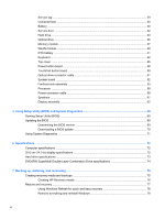
side ...7 Display ...8 Top ...9 TouchPad ...9 Lights ...10 Buttons and speakers ...11 Keys ...12 Bottom ...13 3 Illustrated parts catalog ...15 Service tag ...15 Computer major components ...16 Display assembly subcomponents ...18 Mass storage devices ...20 Miscellaneous parts ...21 Sequential part - HP ENVY dv4-5b00 | HP Envy dv4 Maintenance and Service Guide - Page 6
tag ...29 Computer feet ...30 Battery ...30 Service door ...32 Hard drive ...33 Optical drive ...36 Memory module ...37 Backing up, restoring, and recovering ...75 Creating recovery media and backups 75 Creating HP Recovery media 76 Restore and recovery ...77 Using Windows Refresh for quick and - HP ENVY dv4-5b00 | HP Envy dv4 Maintenance and Service Guide - Page 7
Manager 79 What you need to know 79 Using the HP Recovery partition to recover a minimized image (select models only) ...79 Using HP Recovery media to recover 80 Changing the computer boot order 80 Removing the HP Recovery partition 80 8 Power cord set requirements ...81 Requirements for - HP ENVY dv4-5b00 | HP Envy dv4 Maintenance and Service Guide - Page 8
viii - HP ENVY dv4-5b00 | HP Envy dv4 Maintenance and Service Guide - Page 9
Category Product Name Processor Chipset Graphics Display Panel Memory Description HP Envy dv4 ● Intel® CoreTM i5-3210M 2.5 GHz processor (SC turbo (64 MB x 16 DDR3 900 MHz x 8 PCs); 128 bit M2 29 mm x 29 mm Support HD decode, DX11, HDMI, and PX5.0 35.6 cm (14.0 in), light-emitting diode (LED), - HP ENVY dv4-5b00 | HP Envy dv4 Maintenance and Service Guide - Page 10
6.35 cm (2.5 in) hard drives in 9.5 mm (.37 in) thickness Customer-accessible Serial ATA Intel Smart Response Technology support HP 3D DriveGuard support Supports the following hard drives: ● 1 TB, 5400 rpm, 9.5 mm ● 750 GB, 7200 rpm and 5400 rpm, 9.5 mm ● 500 GB, 7200 rpm and 5400 rpm, 9.5 mm - HP ENVY dv4-5b00 | HP Envy dv4 Maintenance and Service Guide - Page 11
), USB 2.0 (1 port) Full-size, island-style TouchPad with two buttons: ● Multitouch gesture support enabled as default ● Taps enabled by default ● Supports edge-swipe gestures 90 W HP Smart AC adapter (RC, V, PFC, EM, 3-wire) Supports 6-cell, 62 Wh, 2.8 Ah, Li-ion battery (battery is user-removable - HP ENVY dv4-5b00 | HP Envy dv4 Maintenance and Service Guide - Page 12
2 External component identification Finding your hardware and software information Locating hardware To find out what hardware is installed on your computer: 1. From the Start screen, type c, and then select Control Panel. 2. Select System and Security, and then in the System area, click Device - HP ENVY dv4-5b00 | HP Envy dv4 Maintenance and Service Guide - Page 13
Front Component Digital Media Slot Description Supports the following digital card formats: ● Secure Digital (SD) Memory Card ● Secure Digital High Capacity (SDHC) Memory Card ● Secure Digital Extended Capacity (SDxC) Memory Card ● MultiMediaCard (MMC) Front 5 - HP ENVY dv4-5b00 | HP Envy dv4 Maintenance and Service Guide - Page 14
factory. Rapid Start Technology allows your computer to resume quickly from inactivity. ● Blinking white: The hard drive is being accessed. ● Amber: HP 3D DriveGuard has temporarily parked the hard drive. Connects an optional USB device. Connects a network cable. Connects an AC adapter. 6 Chapter - HP ENVY dv4-5b00 | HP Envy dv4 Maintenance and Service Guide - Page 15
Component (9) AC adapter light (10) Security cable slot Left side Description ● White: The AC adapter is connected and the battery is charged. ● Amber: The AC adapter is connected and the battery is charging. ● Off: The computer is using DC power. Attaches an optional security cable to the - HP ENVY dv4-5b00 | HP Envy dv4 Maintenance and Service Guide - Page 16
Record sound. (2) Webcam light On: The webcam is in use. (3) HP TrueVision HD webcam Records video, captures still photographs, allows you to video to your country or region. To access this guide, select the HP Support Assistant app on the Start screen, select My computer, and then select - HP ENVY dv4-5b00 | HP Envy dv4 Maintenance and Service Guide - Page 17
: The TouchPad is off. ● Off: The TouchPad is on. Moves the on-screen pointer and selects or activates items on the screen. The TouchPad also supports edgeswipe gestures. Functions like the left button on an external mouse. Functions like the right button on an external mouse. Top 9 - HP ENVY dv4-5b00 | HP Envy dv4 Maintenance and Service Guide - Page 18
Lights Component (1) Power light (2) Mute light (3) Wireless light (4) Caps lock light (5) TouchPad light Description ● White: The computer is on. ● Blinking white: The computer is in the Sleep state, which is an energy-saving mode. The computer shuts off power to the display and other - HP ENVY dv4-5b00 | HP Envy dv4 Maintenance and Service Guide - Page 19
Buttons and speakers Component (1) Power button (2) Speakers (2) Description ● When the computer is off, press the button to turn on the computer. ● When the computer is in the Sleep state, press the button briefly to exit Sleep. ● When the computer is in Hibernation, press the button briefly - HP ENVY dv4-5b00 | HP Envy dv4 Maintenance and Service Guide - Page 20
Keys Component (1) esc key (2) fn key (3) Windows key (4) b key (5) Action keys (6) Windows applications key Description Displays system information when pressed in combination with the fn key. Executes frequently used system functions when pressed in combination with the esc key or the - HP ENVY dv4-5b00 | HP Envy dv4 Maintenance and Service Guide - Page 21
(2) (3) (4) Component Battery bay Battery release latch Description Holds the battery. Releases the battery from the battery bay and opens the service door. Integrated subwoofer Vents (5) Provides superior bass sound. Enable airflow to cool internal components. NOTE: The computer fan starts up - HP ENVY dv4-5b00 | HP Envy dv4 Maintenance and Service Guide - Page 22
then receive a warning message, remove the module to restore computer functionality, and then contact support through Help and Support. From the Start screen, type h, and then select Help and Support. The service door provides access to the hard drive bay and memory module compartment. 14 Chapter - HP ENVY dv4-5b00 | HP Envy dv4 Maintenance and Service Guide - Page 23
provided on the service tag. The service tag is located inside the battery bay. See Battery on page 30 for battery removal instructions. Item (1) about the product's hardware components. The part number helps a service technician to determine what components and parts are needed. This number - HP ENVY dv4-5b00 | HP Envy dv4 Maintenance and Service Guide - Page 24
Computer major components 16 Chapter 3 Illustrated parts catalog - HP ENVY dv4-5b00 | HP Envy dv4 Maintenance and Service Guide - Page 25
Item (1) (2) (3) (4) (5) (6) (7) (8) (9) (10) (11) (12) (13) (14) (15) (16) Component Spare part number Display assembly: The display assembly is spared at the subcomponent level only. For more display assembly spare part information, see Display assembly subcomponents on page 18. Keyboard In - HP ENVY dv4-5b00 | HP Envy dv4 Maintenance and Service Guide - Page 26
Bluetooth 4.0 Combo Adapter Qualcomm Atheros AR9485 802.11 b/g/n 1×1 WiFi and AR3012 Bluetooth 4.0 Combo Adapter (select models only) Plastics Kit, includes: Service door Wireless cover (includes one captive retention screw, secured by a C-ring) Spare part number 641369-001 652972-001 676654-001 - HP ENVY dv4-5b00 | HP Envy dv4 Maintenance and Service Guide - Page 27
Item (1) (2) (3) (4a) (4b) (5) (6) (7) Component Display bezel (includes 2 rubber screw covers) 35.6 cm (14.0 in), LED. HD, BrightView display panel (includes 2 rubber screw covers) Webcamera/microphone module (includes 2 rubber screw covers) Display Hinge Kit (includes 2 rubber screw covers, and): - HP ENVY dv4-5b00 | HP Envy dv4 Maintenance and Service Guide - Page 28
Mass storage devices Item (1) Component Spare part number Hard drive (does not include the hard drive rubber bracket, hard drive connector cable, or screws) 1 TB, 5400 rpm, 9.5 mm 676521-001 750 GB, 7200 rpm, 9.5 mm 633252-001 750 GB, 5400 rpm, 9.5 mm 634250-001 500 GB, 7200 rpm, 9.5 mm - HP ENVY dv4-5b00 | HP Envy dv4 Maintenance and Service Guide - Page 29
Hardware Kit, includes: Optical drive bezel Optical drive bracket Optical drive connector cable Spare part number 676661-001 681227-001 Miscellaneous parts Component HP Smart AC adapter (90 W, RC, V, PFC, EM, 3-wire) Power cord (3-pin, black, 1.83-m) for use in the People's Republic of China Screw - HP ENVY dv4-5b00 | HP Envy dv4 Maintenance and Service Guide - Page 30
and 2 rubber screw covers) Power button board (includes cable) Plastics Kit (includes service door and wireless module compartment cover) 35.6 cm (14.0 in), LED, HD, (includes 2 base enclosure rear rubber feet) 90 W HP Smart AC adapter (RC, V, PFC, EM, 3-wire) 22 Chapter 3 Illustrated parts catalog - HP ENVY dv4-5b00 | HP Envy dv4 Maintenance and Service Guide - Page 31
Spare part number 694763-501 694771-001 694772-001 699285-001 700547-001 700627-001 703248-001 Description System board (includes replacement thermal material) Top cover in black licorice finish (includes TouchPad and cable) Top cover in carmine red finish (includes TouchPad and cable) Keyboard in - HP ENVY dv4-5b00 | HP Envy dv4 Maintenance and Service Guide - Page 32
plastic parts. Use care when handling the plastic parts. Apply pressure only at the points designated in the maintenance instructions. Cables and connectors CAUTION: When servicing the computer, be sure that cables are placed in their proper locations during the reassembly process. Improper cable - HP ENVY dv4-5b00 | HP Envy dv4 Maintenance and Service Guide - Page 33
Drive handling CAUTION: Drives are fragile components that must be handled with care. To prevent damage to the computer, damage to a drive, or loss of information, observe these precautions: Before removing or inserting a hard drive, shut down the computer. Before handling a drive, be sure that you - HP ENVY dv4-5b00 | HP Envy dv4 Maintenance and Service Guide - Page 34
Event Walking across carpet Walking across vinyl floor Motions of bench worker Removing DIPS from plastic tube Removing DIPS from vinyl tray Removing DIPS from Styrofoam Removing bubble pack from PCB Packing PCBs in foam-lined box Typical electrostatic voltage levels Relative humidity 10% 40% - HP ENVY dv4-5b00 | HP Envy dv4 Maintenance and Service Guide - Page 35
. ● Use a wrist strap connected to a properly grounded work surface and use properly grounded tools and equipment. ● Use conductive field service tools, such as cutters, screwdrivers, and vacuums. ● When fixtures must directly contact dissipative surfaces, use fixtures made only of staticsafe - HP ENVY dv4-5b00 | HP Envy dv4 Maintenance and Service Guide - Page 36
provides removal and replacement procedures. IMPORTANT: There may be as many as 75 screws that must be removed, replaced, and/or loosened when servicing the computer. Make special note of each screw size and location during removal and replacement. 28 Chapter 4 Removal and replacement procedures - HP ENVY dv4-5b00 | HP Envy dv4 Maintenance and Service Guide - Page 37
on the service tag. It is necessary to remove the battery to obtain these numbers. See Battery on page 30 for battery removal instructions. Item about the product's hardware components. The part number helps a service technician determine what components and parts are needed. This number describes - HP ENVY dv4-5b00 | HP Envy dv4 Maintenance and Service Guide - Page 38
Computer feet Description Rubber Feet Kit Spare part number 689843-001 The computer feet are adhesive-backed rubber pads. There are two rubber feet that attach to the base enclosure in the locations illustrated below. Battery Description 6-cell, 62 Wh, 2.8 Ah, Li-ion battery Spare part number - HP ENVY dv4-5b00 | HP Envy dv4 Maintenance and Service Guide - Page 39
4. Remove the battery (3) from the computer. To insert the battery: 1. Align the tabs on the rear edge of the battery (1) with the notches on the rear edge of the battery bay. 2. Pivot the front edge of the battery (2) down into the battery bay until it is fully seated. (The battery release latch - HP ENVY dv4-5b00 | HP Envy dv4 Maintenance and Service Guide - Page 40
the AC outlet and then unplugging the AC adapter from the computer. 4. Remove the battery (see Battery on page 30). Remove the service door: 1. Slide the battery release latch (1) to release the service door. 2. Slide the service door (2) toward the front of the computer. 3. Lift up and remove the - HP ENVY dv4-5b00 | HP Envy dv4 Maintenance and Service Guide - Page 41
by unplugging the power cord from the computer. 3. Disconnect all external devices from the computer. 4. Remove the battery (see Battery on page 30). 5. Remove the service door (see Service door on page 32). Component replacement procedures 33 - HP ENVY dv4-5b00 | HP Envy dv4 Maintenance and Service Guide - Page 42
Remove the hard drive: 1. Using the cable tab (1), carefully lift up and disconnect the hard drive cable from the computer, and then pull the cable out from the routing clips (2). 2. Remove the two Phillips M2.0×3.0 screws (1) that secure the hard drive to the computer. NOTE: When removing the hard - HP ENVY dv4-5b00 | HP Envy dv4 Maintenance and Service Guide - Page 43
3. Use the tab (3) to lift and remove the hard drive from the hard drive bay. 4. If it is necessary to disassemble the hard drive, perform the following steps: a. Separate the front edges of the hard drive rubber bracket (1) from the hard drive b. Remove the hard drive (2) from the bracket. c. If - HP ENVY dv4-5b00 | HP Envy dv4 Maintenance and Service Guide - Page 44
cord from the computer. 3. Disconnect all external devices from the computer. 4. Remove the battery (see Battery on page 30). 5. Remove the service door (see Service door on page 32). Remove the optical drive: 1. Remove the Phillips M2.5×7.0 screw (1) that secures the optical drive to the computer - HP ENVY dv4-5b00 | HP Envy dv4 Maintenance and Service Guide - Page 45
5. Use a flat-blade screw driver or similar tool to press on the optical drive bezel tab (2) to release the optical drive bezel. 6. Release the left side of the optical drive bezel (3). 7. Remove the optical drive bezel (4). 8. If it is necessary to replace the optical drive bracket, position the - HP ENVY dv4-5b00 | HP Envy dv4 Maintenance and Service Guide - Page 46
power cord from the computer. 3. Disconnect all external devices from the computer. 4. Remove the battery (see Battery on page 30). 5. Remove the service door (see Service door on page 32). Remove the memory module: 1. Spread the retaining tabs (1) on each side of the memory module slot to release - HP ENVY dv4-5b00 | HP Envy dv4 Maintenance and Service Guide - Page 47
, remove the module to restore device functionality, and then contact technical support. Before removing the WLAN module, follow these steps: 1. Shut down Remove the battery (see Battery on page 30). 5. Remove the service door (see Service door on page 32). Remove the WLAN module: 1. Loosen the - HP ENVY dv4-5b00 | HP Envy dv4 Maintenance and Service Guide - Page 48
4. Disconnect the WLAN antenna cables (1) from the terminals on the WLAN module. NOTE: The #1 WLAN antenna cable is connected to the WLAN module "Main" terminal. The #2 WLAN antenna cable is connected to the WLAN module "Aux" terminal. 5. Remove the two Phillips M2.0×3.5 screws (2) that secure the - HP ENVY dv4-5b00 | HP Envy dv4 Maintenance and Service Guide - Page 49
cord from the computer. 3. Disconnect all external devices from the computer. 4. Remove the battery (see Battery on page 30). 5. Remove the service door (see Service door on page 32). 6. Remove the wireless module compartment cover (see WLAN module on page 39). Remove the RTC battery: 1. Use a flat - HP ENVY dv4-5b00 | HP Envy dv4 Maintenance and Service Guide - Page 50
cord from the computer. 3. Disconnect all external devices from the computer. 4. Remove the battery (see Battery on page 30). 5. Remove the service door (see Service door on page 32). Remove the keyboard: 1. Remove the two Phillips M2.5×6.5 screws that secure the keyboard to the computer. 2. Rest - HP ENVY dv4-5b00 | HP Envy dv4 Maintenance and Service Guide - Page 51
4. Insert a thin tool into the left retention screw hole, and then press on the back of the keyboard until the keyboard disengages from the computer. 5. Turn the computer right-side up with the front toward you. 6. Lift the rear edge of the keyboard (1), and then swing the keyboard (2) up and - HP ENVY dv4-5b00 | HP Envy dv4 Maintenance and Service Guide - Page 52
8. Remove the keyboard (3). Reverse this procedure to install the keyboard. 44 Chapter 4 Removal and replacement procedures - HP ENVY dv4-5b00 | HP Envy dv4 Maintenance and Service Guide - Page 53
see Battery on page 30), and then remove the following components: a. Service door (see Service door on page 32) b. Hard drive (see Hard drive on page 48 and TouchPad button board on page 50 for removal and replacement instructions for these components. Remove the top cover: 1. Remove the two rear - HP ENVY dv4-5b00 | HP Envy dv4 Maintenance and Service Guide - Page 54
3. Remove the seven Phillips M2.0×3.5 screws that secure the top cover to the computer. 4. Turn the computer right side up, with the front toward you. 5. Open the computer. 6. Release the ZIF connector to which the power button board cable is connected, and then disconnect the power button board (1) - HP ENVY dv4-5b00 | HP Envy dv4 Maintenance and Service Guide - Page 55
9. Remove the two Phillips M2.0×3.5 screws (2) that secure the top cover to the computer. 10. Use a thin plastic tool to release the top cover. Insert the tool between the top cover and base enclosure and slide the tool as shown from the following points: a. Between the VGA and HDMI connectors (1) - HP ENVY dv4-5b00 | HP Envy dv4 Maintenance and Service Guide - Page 56
. 3. Disconnect all external devices from the computer. 4. Remove the battery (see Battery on page 30), and then remove the following components: a. Service door (see Service door on page 32) b. Hard drive (see Hard drive on page 33) c. Optical drive (see Optical drive on page 36) d. Keyboard - HP ENVY dv4-5b00 | HP Envy dv4 Maintenance and Service Guide - Page 57
4. Remove the power button board (3) and cable. Reverse this procedure to install the power button board. Component replacement procedures 49 - HP ENVY dv4-5b00 | HP Envy dv4 Maintenance and Service Guide - Page 58
. 3. Disconnect all external devices from the computer. 4. Remove the battery (see Battery on page 30), and then remove the following components: a. Service door (see Service door on page 32) b. Hard drive (see Hard drive on page 33) c. Optical drive (see Optical drive on page 36) d. Keyboard - HP ENVY dv4-5b00 | HP Envy dv4 Maintenance and Service Guide - Page 59
. 3. Disconnect all external devices from the computer. 4. Remove the battery (see Battery on page 30), and then remove the following components: a. Service door (see Service door on page 32) b. Hard drive (see Hard drive on page 33) c. Optical drive (see Optical drive on page 36) d. Keyboard - HP ENVY dv4-5b00 | HP Envy dv4 Maintenance and Service Guide - Page 60
computer. 3. Disconnect all external devices from the computer. 4. Remove the battery (see Battery on page 30), and then remove the following components: a. Service door (see Service door on page 32) b. Hard drive (see Hard drive on page 33) c. Optical drive (see Optical drive on page 36) d. WLAN - HP ENVY dv4-5b00 | HP Envy dv4 Maintenance and Service Guide - Page 61
Remove the system board: 1. Disconnect the following cables from the system board: (1) Display panel cable (2) Speaker cable (3) Optical drive connector cable (4) Power connector cable 2. Remove the three Phillips M2.0×5.0 screws (1) that secure the system board to the base enclosure. 3. Lift the - HP ENVY dv4-5b00 | HP Envy dv4 Maintenance and Service Guide - Page 62
4. Remove the system board (3) by sliding it up and to the right at an angle. Reverse this procedure to install the system board. 54 Chapter 4 Removal and replacement procedures - HP ENVY dv4-5b00 | HP Envy dv4 Maintenance and Service Guide - Page 63
computer. 3. Disconnect all external devices from the computer. 4. Remove the battery (see Battery on page 30), and then remove the following components: a. Service door (see Service door on page 32) b. Hard drive (see Hard drive on page 33) c. Optical drive (see Optical drive on page 36) d. WLAN - HP ENVY dv4-5b00 | HP Envy dv4 Maintenance and Service Guide - Page 64
/heat sink assembly, processor, and system board spare part kits. ● Thermal paste is used on the processor (1) and the fan/heat sink assembly section (2) that services it ● Thermal paste is used on the graphics subsystem chip (3) and the fan/heat sink assembly section (4) that - HP ENVY dv4-5b00 | HP Envy dv4 Maintenance and Service Guide - Page 65
Reverse this procedure to install the fan/heat sink assembly. Component replacement procedures 57 - HP ENVY dv4-5b00 | HP Envy dv4 Maintenance and Service Guide - Page 66
computer. 3. Disconnect all external devices from the computer. 4. Remove the battery (see Battery on page 30), and then remove the following components: a. Service door (see Service door on page 32) b. Hard drive (see Hard drive on page 33) c. Optical drive (see Optical drive on page 36) d. WLAN - HP ENVY dv4-5b00 | HP Envy dv4 Maintenance and Service Guide - Page 67
computer. 3. Disconnect all external devices from the computer. 4. Remove the battery (see Battery on page 30), and then remove the following components: a. Service door (see Service door on page 32) b. Hard drive (see Hard drive on page 33) c. Optical drive (see Optical drive on page 36) d. WLAN - HP ENVY dv4-5b00 | HP Envy dv4 Maintenance and Service Guide - Page 68
Remove the power connector cable: 1. Remove the Phillips M2.5×6.5 screw (1) and the two Phillips M2.0×5.0 screws (2) that secure the power connector bracket to the base enclosure. 2. Remove the power connector bracket (3). 3. Release the power connector (4) from the clip built into the base - HP ENVY dv4-5b00 | HP Envy dv4 Maintenance and Service Guide - Page 69
computer. 3. Disconnect all external devices from the computer. 4. Remove the battery (see Battery on page 30), and then remove the following components: a. Service door (see Service door on page 32) b. Hard drive (see Hard drive on page 33) c. Optical drive (see Optical drive on page 36) d. WLAN - HP ENVY dv4-5b00 | HP Envy dv4 Maintenance and Service Guide - Page 70
4. Remove the speakers (3). NOTE: The speakers include four rubber isolators that are installed in the screw holes (4). These isolators are crucial to the performance of the speakers. Reverse this procedure to install the speakers. Display assembly NOTE: The display assembly is spared at the - HP ENVY dv4-5b00 | HP Envy dv4 Maintenance and Service Guide - Page 71
battery (see Battery on page 30), and then remove the following components: a. Service door (see Service door on page 32) b. Hard drive (see Hard drive on page 33) right speaker. CAUTION: Support the display assembly when removing the following screws. Failure to support the display assembly can - HP ENVY dv4-5b00 | HP Envy dv4 Maintenance and Service Guide - Page 72
3. Remove the display assembly (2). 4. If it is necessary to replace the display bezel or any of the display assembly subcomponents: a. Remove the two display bezel screw covers (1) and the two Phillips M2.5×5.0 screws (2) that secure the display bezel to the display assembly. b. Flex the inside - HP ENVY dv4-5b00 | HP Envy dv4 Maintenance and Service Guide - Page 73
to the display enclosure. b. Lift the top edge of the display panel (2) and turn the display panel upside down. c. Release the adhesive support strip (1) that secures the display panel cable connector to the display panel. d. Disconnect the display panel cable (2) from the display panel. e. Remove - HP ENVY dv4-5b00 | HP Envy dv4 Maintenance and Service Guide - Page 74
b. Detach the webcamera/microphone module (2) from the display enclosure. (The webcamera/microphone module is attached to the display enclosure by doublesided tape.) c. Remove the webcamera/microphone module from the display enclosure. 7. If it is necessary to replace the hinges: a. Remove the four - HP ENVY dv4-5b00 | HP Envy dv4 Maintenance and Service Guide - Page 75
c. Remove the hinges (3) from the display enclosure. 8. If it is necessary to replace the display panel cable: a. Release the display panel cable from the clips (1) and routing channel built into the display enclosure. b. Remove the display panel cable (2). 9. If it is necessary to replace the - HP ENVY dv4-5b00 | HP Envy dv4 Maintenance and Service Guide - Page 76
c. Remove the wireless antenna cables and transceivers (3). Reverse this procedure to install the display assembly. 68 Chapter 4 Removal and replacement procedures - HP ENVY dv4-5b00 | HP Envy dv4 Maintenance and Service Guide - Page 77
Setup Utility (BIOS). Errors can prevent the computer from operating properly. Updating HP website. Most BIOS updates on the HP website are packaged in compressed files called SoftPaqs. Some download packages contain a file named Readme.txt, which contains information regarding installing and troubleshooting - HP ENVY dv4-5b00 | HP Envy dv4 Maintenance and Service Guide - Page 78
or disconnect any device, cable, or cord. 1. From the Start screen, select the HP Support Assistant app. 2. Click Updates and tune-ups, and then click Check for HP updates now. 3. Follow the on-screen instructions. 4. At the download area, follow these steps: a. Identify the most recent BIOS update - HP ENVY dv4-5b00 | HP Envy dv4 Maintenance and Service Guide - Page 79
or restart the computer, quickly press esc, and then press f2. 2. Click the diagnostic test you want to run, and then follow the on-screen instructions. NOTE: If you need to stop a diagnostic test while it is running, press esc. Using System Diagnostics 71 - HP ENVY dv4-5b00 | HP Envy dv4 Maintenance and Service Guide - Page 80
6 Specifications Computer specifications Metric U.S. Dimensions Width 34.4 cm 13.54 in Depth 23.4 cm 9.21 in Height (front to back) 2.93 to 3.35 cm 1.15 to 1.32 in Weight 2.17 kg 4.79 lb Input power Operating voltage and current 19 V @ 4.74 A or 19.5 V @ 4.62 A - 90 W Temperature - HP ENVY dv4-5b00 | HP Envy dv4 Maintenance and Service Guide - Page 81
is less. **1 GB = 1 billion bytes when referring to hard drive storage capacity. Actual accessible capacity is less. NOTE: Certain restrictions and exclusions apply. Contact technical support for details. Hard drive specifications 73 - HP ENVY dv4-5b00 | HP Envy dv4 Maintenance and Service Guide - Page 82
DVD±RW SuperMulti Double-Layer Combination Drive specifications Applicable disc Read Write Random access time DVD CD Cache buffer Data transfer rate 24X CD-ROM 8X DVD-ROM 24X CD-R 16X CD-RW 8X DVD+R 4X DVD+RW 8X DVD-R 4X DVD-RW 2.4X DVD+R(9) 5X DVD-RAM Transfer mode CD-DA, CD+(E)G, CD-MIDI, CD- - HP ENVY dv4-5b00 | HP Envy dv4 Maintenance and Service Guide - Page 83
NOTE: This guide describes an Support. Creating recovery media and backups Recovery after a system failure is only as good as your most recent backup. 1. After you successfully set up the computer, create HP Recovery media. This step creates a backup of the HP You can also manually create a system - HP ENVY dv4-5b00 | HP Envy dv4 Maintenance and Service Guide - Page 84
from the HP website. For U.S. support, go to http://www.hp.com/go/contactHP. For worldwide support, go to http://welcome.hp.com/ HP Recovery media: 1. From the Start screen, type recovery, and then select HP Recovery Manager. 2. Select Recovery Media Creation, and follow the on-screen instructions - HP ENVY dv4-5b00 | HP Envy dv4 Maintenance and Service Guide - Page 85
Support. ● If you need to correct a problem with a preinstalled application or driver, use the Drivers and Applications Reinstall option of HP HP Recovery Manager, and then select Drivers and Applications Reinstall, and follow the on-screen instructions if you did not manually create a restore point, - HP ENVY dv4-5b00 | HP Envy dv4 Maintenance and Service Guide - Page 86
. See Windows Help and Support for more information. From the Start screen, type h, and then select Help and Support. To start Refresh: press the power button. 2. Select Troubleshoot from the boot options menu. 3. Select Reset your PC, and follow the on-screen instructions. To use the Start screen: - HP ENVY dv4-5b00 | HP Envy dv4 Maintenance and Service Guide - Page 87
working. To start HP Recovery Manager from the HP Recovery partition: 1. Press f11 while the computer boots. - or - Press and hold f11 as you press the power button. 2. Select Troubleshoot from the boot options menu. 3. Select HP Recovery Manager, and follow the on-screen instructions. Restore and - HP ENVY dv4-5b00 | HP Envy dv4 Maintenance and Service Guide - Page 88
, change the computer boot order. See Changing the computer boot order on page 80. 3. Follow the on-screen instructions. Changing the computer boot order If computer does not restart in HP Recovery Manager, you can change the computer boot order, which is the order of devices listed in BIOS where - HP ENVY dv4-5b00 | HP Envy dv4 Maintenance and Service Guide - Page 89
8 Power cord set requirements The wide-range input feature of the computer permits it to operate from any line voltage from 100 to 120 volts ac, or from 220 to 240 volts ac. The 3-conductor power cord set included with the computer meets the requirements for use in the country or region where the - HP ENVY dv4-5b00 | HP Envy dv4 Maintenance and Service Guide - Page 90
Requirements for specific countries and regions Country/region Argentina Australia Austria Belgium Brazil Canada Chile Denmark Finland France Germany India Israel Italy Japan The Netherlands New Zealand Norway The People's Republic of China Saudi Arabia Singapore South Africa South Korea Sweden - HP ENVY dv4-5b00 | HP Envy dv4 Maintenance and Service Guide - Page 91
Country/region Accredited agency Applicable note number The United States UL 2 1. The flexible cord must be Type HO5VV-F, 3-conductor, 0.75 mm² conductor size. Power cord set fittings (appliance coupler and wall plug) must bear the certification mark of the agency responsible for evaluation in - HP ENVY dv4-5b00 | HP Envy dv4 Maintenance and Service Guide - Page 92
dispose of the battery in general household waste. Follow the local laws and regulations in your area for battery disposal. HP encourages customers to recycle used electronic hardware, HP original print cartridges, and rechargeable batteries. For more information about recycling programs, see the - HP ENVY dv4-5b00 | HP Envy dv4 Maintenance and Service Guide - Page 93
changing HP Recovery Manager 80 bottom components 13 buttons optical drive eject 6 power 11 TouchPad 9 TouchPad on/off 9 C cables, service considerations reset 78 computer specifications 72 connector, power 6 connectors, service considerations 24 D deleted files restoring 77 Digital Media Slot, - HP ENVY dv4-5b00 | HP Envy dv4 Maintenance and Service Guide - Page 94
port, identifying 7 HP Recovery Manager 79 correcting boot problems 80 starting 79 HP Recovery media creating 76 recovery 80 HP Recovery partition 79 recovery 79 P packaging guidelines 27 part number 29 location 15 plastic parts, service considerations 24 Plastics Kit 32 spare part number 18, 22, 32 - HP ENVY dv4-5b00 | HP Envy dv4 Maintenance and Service Guide - Page 95
serviceability 3 video 2 wireless 2 product name 1, 29 location 15 product number 29 location 15 R recovery 77, 78 discs 76, 80 HP Recovery Manager 79 media 80 starting 79 supported 3.0 ports, identifying 7 USB ports, identifying 6 user guides accessing 8 V vents, identifying 7, 13 video, product - HP ENVY dv4-5b00 | HP Envy dv4 Maintenance and Service Guide - Page 96
Refresh 77, 78 reinstall 77, 78 remove everything and reinstall option 78 reset 78 restoring files 77 system restore point 75, 77 Windows applications key, identifying 12 Windows key, identifying 12 wireless antenna locations 8 removal 67 spare part number 19, 22, 62 wireless light 10 wireless
-
 1
1 -
 2
2 -
 3
3 -
 4
4 -
 5
5 -
 6
6 -
 7
7 -
8
-
9
-
10
-
11
-
12
-
13
-
14
-
15
-
16
-
17
-
18
-
19
-
20
-
21
-
22
-
23
-
24
-
25
-
26
-
27
-
28
-
29
-
30
-
31
-
32
-
33
-
34
-
35
-
36
-
37
-
38
-
39
-
40
-
41
-
42
-
43
-
44
-
45
-
46
-
47
-
48
-
49
-
50
-
51
-
52
-
53
-
54
-
55
-
56
-
57
-
58
-
59
-
60
-
61
-
62
-
63
-
64
-
65
-
66
-
67
-
68
-
69
-
70
-
71
-
72
-
73
-
74
-
75
-
76
-
77
-
78
-
79
-
80
-
81
-
82
-
83
-
84
-
85
-
86
-
87
-
88
-
89
-
90
-
91
-
92
-
93
-
94
-
95
-
96
 |
 |

HP Envy dv4
Maintenance and Service Guide